
Electro-magnetically operated bolt

Inactive Publication Date: 2006-01-12
PLANET ECLIPSE
View PDF71 Cites 17 Cited by
  • Summary
  • Abstract
  • Description
  • Claims
  • Application Information

AI Technical Summary

Benefits of technology

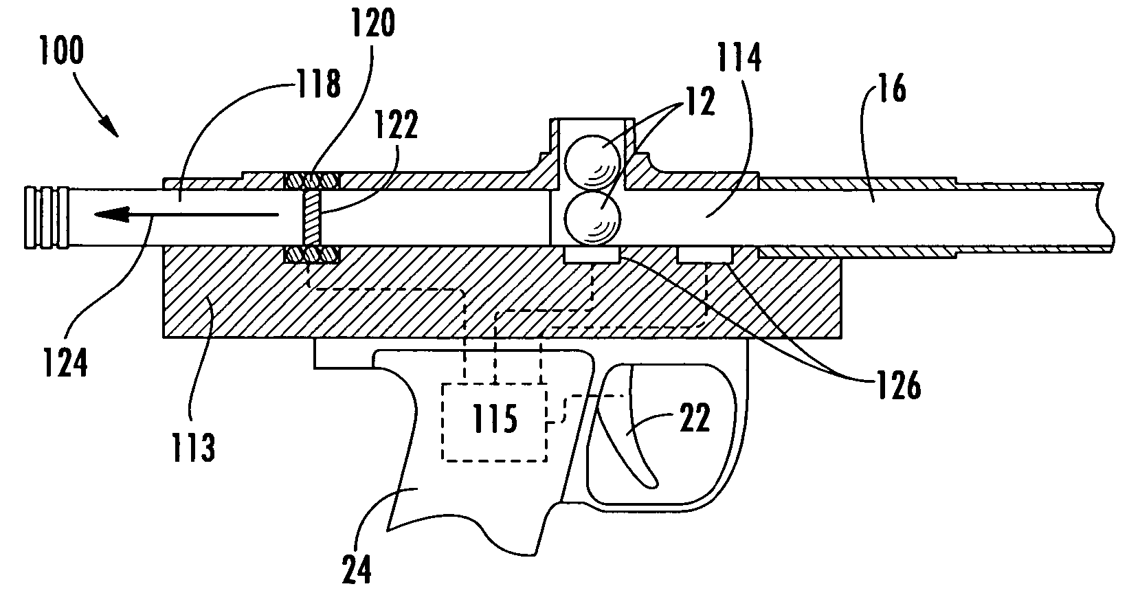
[0009] In this regard, the present invention provides for a novel bolt mechanism that overcomes many of the problems with the prior art bolts identified above. In particular, the present invention provides a bolt mechanism that is actuated by an electro-magnetic arrangement, which provides for rapid movement of the bolt as well as a high degree of control over the bolt. The use of electromagnetic force instead of electronic solenoids and a pneumatic piston to actuate the bolt in a marker is a departure from the known prior art and provides numerous advantages that result in a marker having higher reliability and improved performance.
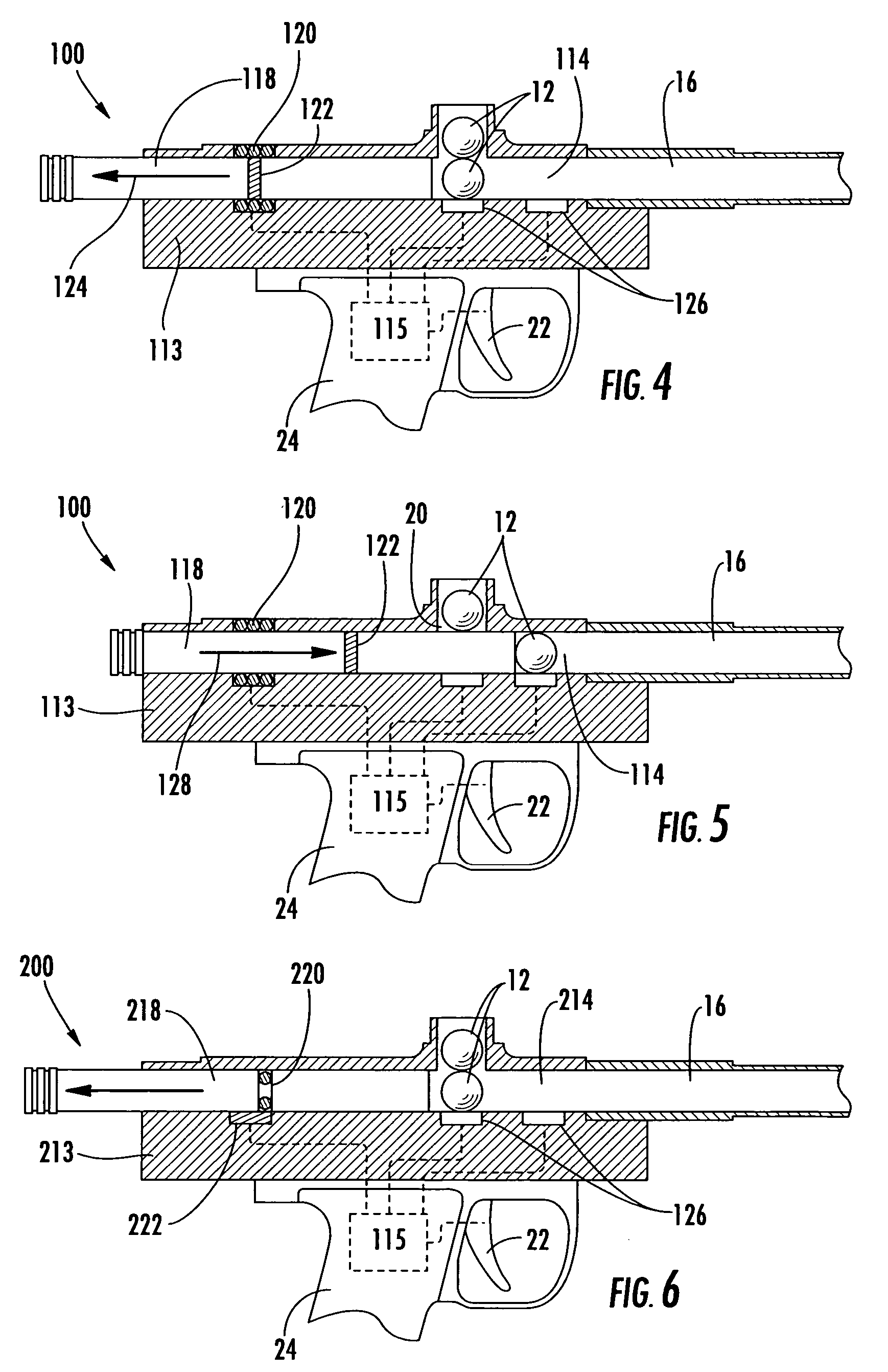
[0010] As will be discussed in detail below, the base concept of the present invention is to utilize an arrangement of electromagnetic coils that exert a force on ferrous materials or permanent magnets thereby causing the bolt to reciprocate back and forth. In one embodiment, a piece of ferrous material or a permanent magnet is installed into the body of the bolt and at least one electro-magnetic coil is installed in the wall of the breach adjacent the bolt. Application of an electrical charge to the electromagnetic coil serves to attract or repel the magnet in the bolt, causing the bolt to be moved. In other embodiments, at least one coil is provided in the body of the bolt and at least one magnet or piece of ferrous material is installed in the wall of the breech, adjacent the bolt. In further embodiments, multiple electro-magnetic coils are utilized to increase the overall force exerted on the permanent magnet or ferrous material, thereby enhancing the speed at which the bolt can be moved. In another embodiment, the magnet or ferrous material is positioned adjacent the bolt in a chamber of its own with electro-magnetic coils placed within the walls of the chamber. The magnet or ferrous material is connected to the bolt by a linkage so that movement of the magnet or ferrous material results in movement of the bolt. In yet a further embodiment, the present invention provides for a rotary action bolt that includes at least one permanent magnet or piece of ferrous material mounted therein with an array of electromagnetic coils disposed around the wall of the breech surrounding the bolt. As each of the electromagnetic coils is activated by applying an electrical charge, the coils attract or repel the magnet or ferrous material, causing the rotary bolt to rotate.
[0011] In addition to the electromagnetic system as described above, various sensors may also be incorporated into the marker and electrically coupled to the control system within the marker thereby providing unprecedented control over the bolt that was not previously possible with known pneumatic systems. As a result, the electronic operating system of the marker can more precisely control the loading and launching of the projectile.
[0012] As can be seen in view of the above, a new and novel electro-magnet bolt control system is provided. Further, a new and novel method of actuating a bolt within a marker without the use of pneumatics or electronically operated solenoid valves is shown. The use of electromagnetic force as provided in the present invention allows for precise control of the travel of the bolt within a marker unlike the poor control capable of with a pneumatically piston-controlled bolt.
[0013] It is therefore an object of the present invention to provide an electro-magnetically operated bolt transport system for use in a pneumatic projectile launcher or marker. It is a further object of the present invention to provide an electro-magnetically operated bolt, wherein electromagnetic coils are utilized to attract and / or repel a piece of ferrous material or permanent magnet thereby causing movement of the bolt. It is yet a further object of the present invention to provide an electro-magnetically operated bolt, wherein multiple electromagnetic coils are utilized in conjunction to move a piece of ferrous material or permanent magnet thereby causing movement of the bolt. It is an even further object of the present invention to provide an electro-magnetic bolt control system that is equally applicable to both a slide bolt and a rotary bolt. It is still a further object of the present invention to provide sensors that are integrated with an electro-magnetically operated bolt system to facilitate a high degree of control over the movement of the bolt.

Problems solved by technology

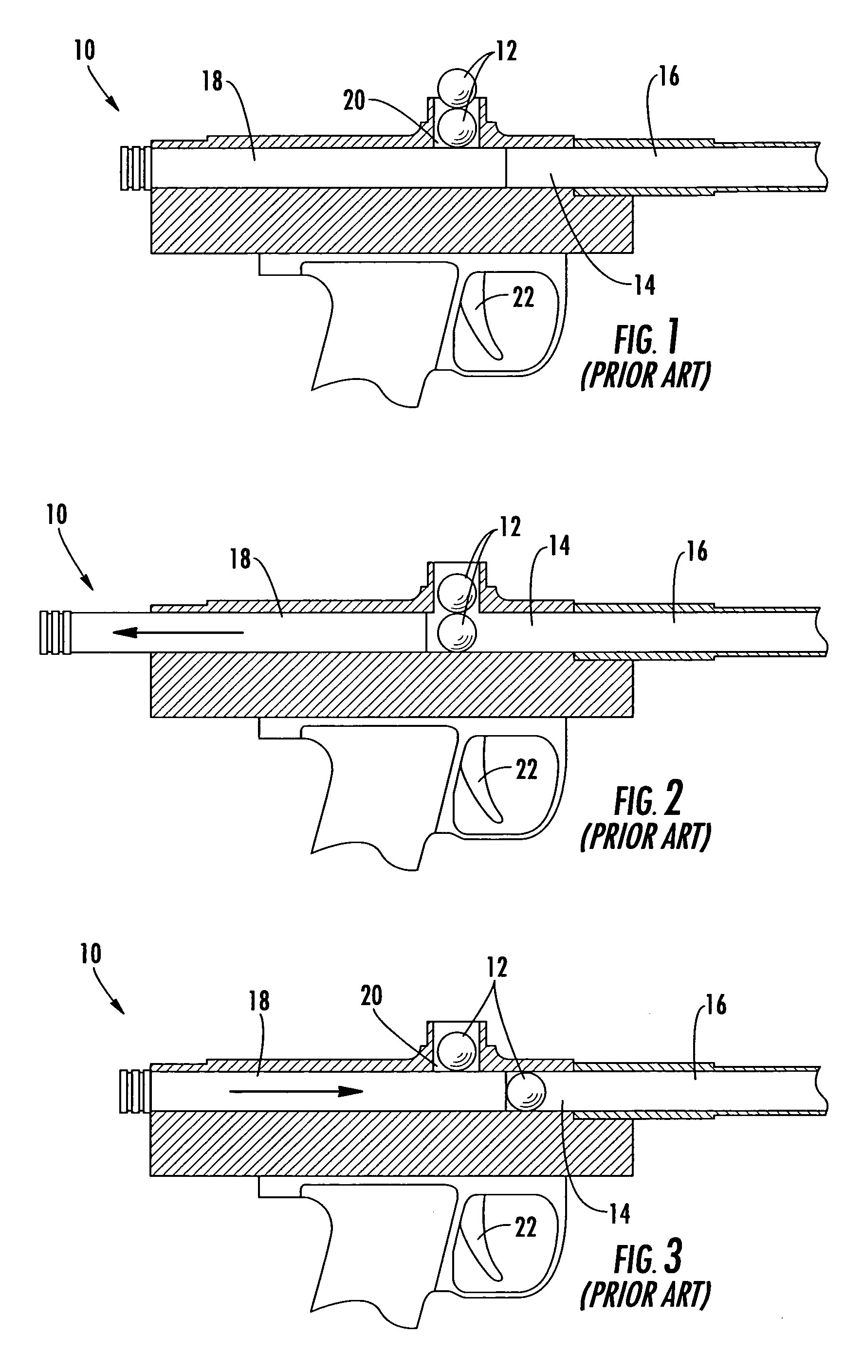
The difficulty is that markers that rely on mechanically or pneumatically driven reciprocating bolts suffer from mechanical limitations that inherently limit the maximum rate of fire that the marker can achieve.
Specifically, the ultimate cycle speed of a pneumatically operated bolt is limited by the speed at which the solenoids in the air system can be sequentially opened and closed.

Method used


Image

  • Electro-magnetically operated bolt
  • Electro-magnetically operated bolt
  • Electro-magnetically operated bolt

Examples


second embodiment

[0030] A second embodiment marker 200 that utilizes the principals of the present invention is shown in FIG. 6. The bolt assembly 218 in this embodiment functions in the same manner as the one described above. In this embodiment however, the positioning of the electromagnetic coil 220 and permanent magnet 222 have been reversed. The permanent magnet 222 is installed in the sidewall of the breech 214 and the coil 220 is positioned in the bolt 218. When electrical current is applied to the coil 220 in one direction, the coil 220 is energized causing a magnetic field that creates an attractive force between the permanent magnet 222 and the coil 220. Since the permanent magnet 222 is in a fixed location and the bolt 218 can slide, the attractive force causes the bolt 218 to slide to an open position allowing a projectile 12 to drop from the feed port 20 into the breech 214. As described above, when the polarity of the current applied to the coil 220 is reversed, the coil 220 repels the ...

third embodiment

[0031] It can be appreciated that in the configurations described above wherein a single coil is utilized, the coil must be used in conjunction with a permanent magnet so that the coil and magnet can interact to attract and / or repel one another. In other embodiments as will be described below, multiple coils may be utilized to attract and repel a permanent magnet. Further, should multiple coils be utilized, the magnet may be replaced with any ferrous material that is attracted by a magnetic field thereby allowing the coils to be operated in single direction to attract the ferrous material. For example, FIGS. 7 and 8 show a marker 300 in accordance with the electro-magnetic bolt system 318 of the present invention where a front coil 320b and rear coil 320a have been installed in the wall of the breech 314. If a permanent magnet 322 is installed into the bolt 318, the front coil 320b can be energized to repel the magnet 322 and the rear coil 320a can be energized to attract the magnet...

fourth embodiment

[0034] Turning now to FIG. 9, a marker 400 in accordance with the present invention is shown wherein an actuator chamber 402 is provided in the receiver body 413 adjacent the breech 414. A linkage 404 extends from the bolt 418 into the actuator chamber 402 and terminates in either a permanent magnet 422 or a piece of ferrous material. Electro-magnetic coils 420 are provided preferably at both ends of the actuator chamber 402, although one coil 420 may be utilized. In the same manner as described in detail above, the coils 420 are used to either attract or repel the magnet 422 or ferrous material thereby causing the linkage 404 and the bolt 418 to be moved as desired by the controller 115.


PUM


Abstract

A bolt mechanism that is actuated by an electromagnetic arrangement is provided for use within a pneumatic projectile launcher or marker. The electro-magnetic arrangement provides for rapid movement and a high degree of control over the bolt. Generally, an arrangement of electro-magnetic coils is provided that exert a force on ferrous materials or permanent magnets thereby causing the bolt to reciprocate back and forth. Several embodiments are provided that disclose configurations having varied numbers of electromagnetic coils, ferrous materials and permanent magnets strategically placed within the breech and bolt of the marker, wherein energizing the coils produces movement of the bolt. Further, the electro-magnetic bolt system of the present invention is equally applicable to slide bolts as well as rotary bolts.

Description

CROSS-REFERENCE TO RELATED APPLICATIONS [0001] This application is related to and claims priority from earlier filed U.S. Provisional Patent Application No. 60 / 545,400, filed Feb. 17, 2004, the contents of which are incorporated herein by reference.BACKGROUND OF THE INVENTION [0002] The present invention relates generally to pneumatically operated projectile launchers. More specifically, the present invention relates to an electro-magnetically operated bolt configuration for use in firearms and other projectile launchers, such as pneumatically operated projectile launchers. [0003] In general, in the prior art, it is well known to utilize a pneumatically operated projectile launcher to propel a projectile at a target. Further, such a device is typically referred to as either a paintball gun or a marker. Accordingly, for the purpose of this application, the term marker will be utilized throughout this application to define a paintball gun or a pneumatically operated projectile launche...

Claims


Application Information

Patent Timeline
IPC IPC(8): F41B11/00F41B11/12F41B11/32
CPCF41B11/64F41B11/57F41B11/71
Inventor MONKS, STEVEN JOHN
Owner PLANET ECLIPSE
Learn More