Fluid filled type vibration damping device

Active Publication Date: 2009-03-26
TOKAI RUBBER IND LTD
View PDF10 Cites 19 Cited by
  • Summary
  • Abstract
  • Description
  • Claims
  • Application Information

AI Technical Summary

Benefits of technology

[0019]According to another preferred mode of the fluid filled type vibration damping device of the present invention, an electromagnetic actuator furnished with a coil member and an output member that receives actuating force through flow of electrical current to the coil member is used as the actuating member for actuating oscillation of the oscillating plate, with the electromagnetic actuator disposed on an opposite side of the oscillating plate from the pressure-receiving chamber, and with the output member penetrating through the flexible film and linked to the oscillating plate. According to this construction, a high degree of control of the oscillation mode and position of the oscillating plate can be possible through control of current flow to the coil member. Thus, in addition to affording consistent oscillating force, the oscillating plate can be rapidly displaced to the position abutting the stopper so that the gap between the oscillating plate and the through-hole can be rapidly closed.
[0020]According to another preferred mode of the fluid filled type vibration damping device of the present invention, a plate spring that extends in an axis-perpendicular direction is positioned between the oscillating plate and the partition member, with the oscillating plate being elastically linked to and supported in the axial direction on the partition member through the plate spring. According to this construction, axis-perpendicular direction displacement and twisting displacement of the oscillating plate with respect to the partition member can be suppressed, and a satisfactory gap may be maintained all the way around the circumference between the outside peripheral face of the oscillating plate and the inside peripheral face of the through-hole, thus effectively preve

Problems solved by technology

However, one problem with such devices was that in order to for each of the orifice passages to achieve the orifice effect effectively, each orifice passage is limited to a pre-tuned, relatively narrow frequency range.
Thus, in instances where frequency or other characteristic of vibration targeted for damping varies, or where advanced vibration damping action is required, difficultly in achieving satisfactory vibration damping action was a problem.
For this reason, there was a risk that permanent set in fatigue of the supporting rubber elastic body might make it difficult to consistently achieve the desired vibration damping action.
Additionally, since oscillation energy of the oscillating plate is consumed through deformation of the supporting rubber elastic body, there is a risk of diminished actuation efficiency of the oscillating plate.
However, a fluid filled vibration damping device furnished with such a piston shaped oscilla

Method used


Image

  • Fluid filled type vibration damping device
  • Fluid filled type vibration damping device
  • Fluid filled type vibration damping device

Examples


Example

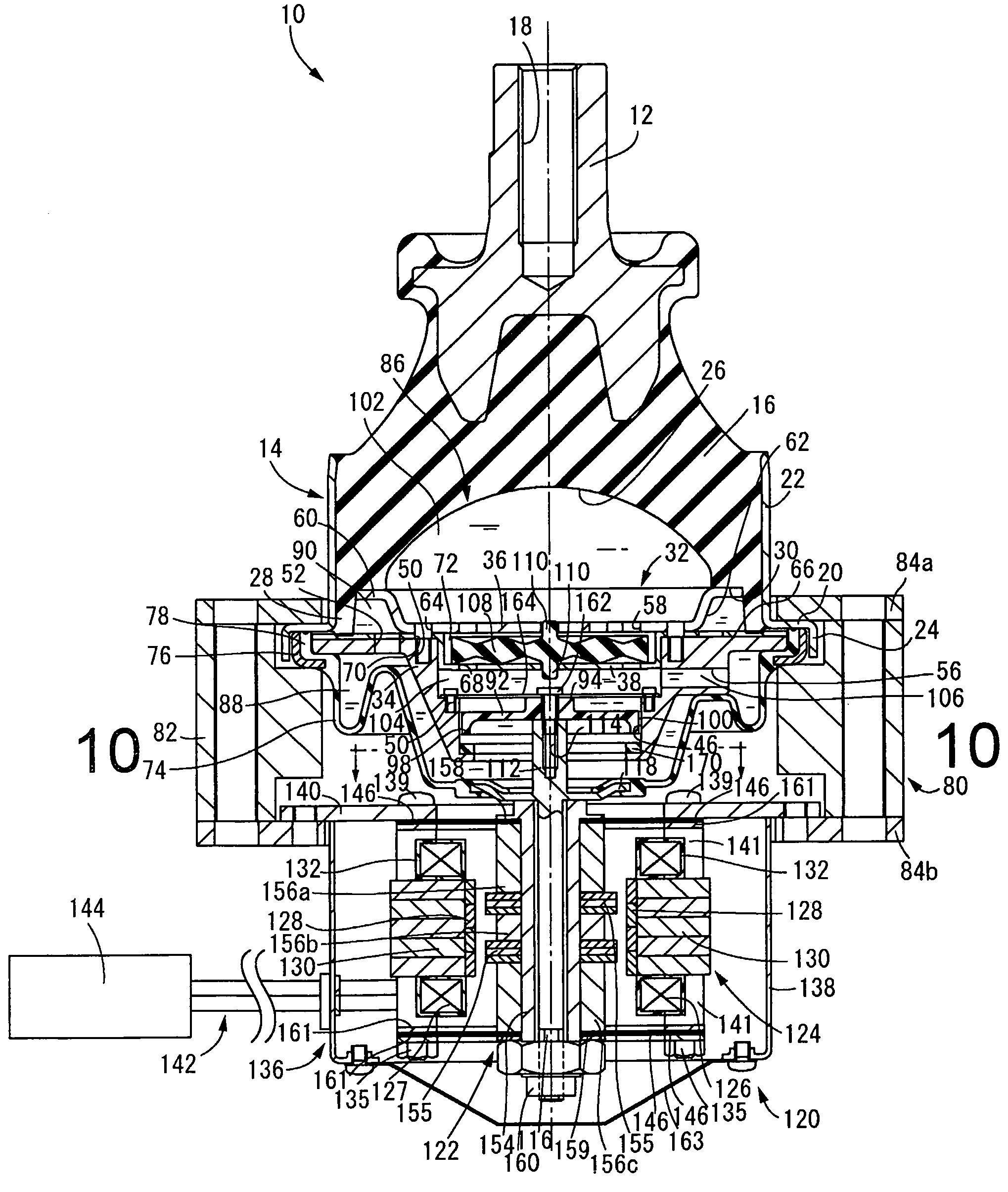
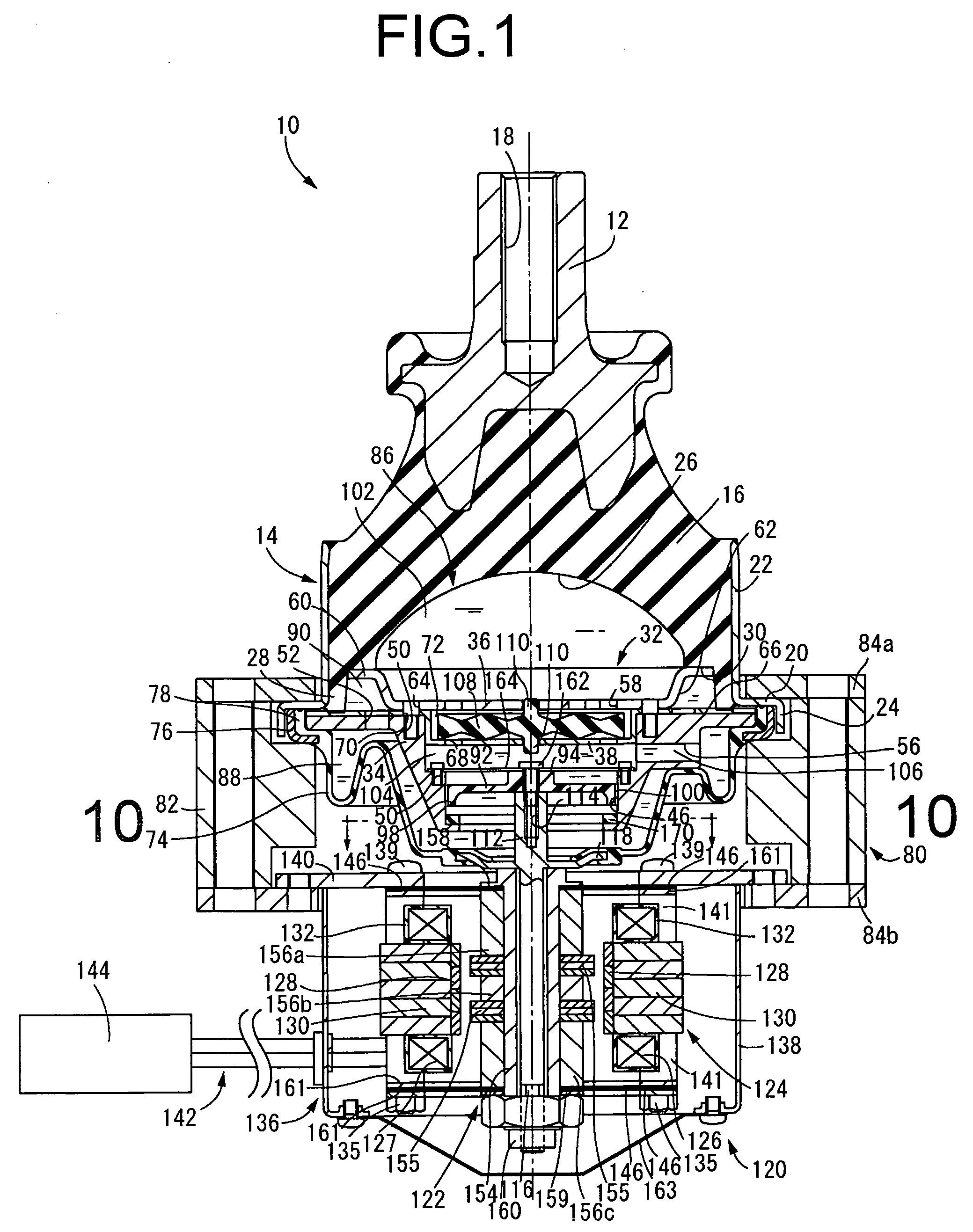
[0035]Referring first to FIG. 1, there is depicted an automotive engine mount 10 according to one embodiment of a fluid-filled type vibration damping device of the present invention. This engine mount 10 has a construction wherein a first mounting member 12 of metal and a second mounting member 14 of metal are linked by a main rubber elastic body 16. The first mounting member 12 is adapted to be mounted onto the vehicle's power unit (not shown), and the second mounting member 14 is adapted to be mounted onto an automobile body (not shown). The power unit is thereby elastically supported on the vehicle body via the intervening engine mount 10.

[0036]Whereas FIG. 1 depicts the engine mount 10 in isolation prior to installation in a vehicle, with the engine mount 10 installed in the vehicle, distributed load of the power unit is input in the mount axial direction (the vertical direction in FIG. 1), thereby inducing displacement of the first mounting member 12 and the second mounting mem...


PUM


Abstract

A vibration damping device including: a pressure-receiving chamber and an equilibrium chamber connected by a first orifice passage; a movable member disposed within the pressure-receiving chamber, to form a primary fluid chamber partly defined by a rubber elastic body, and an auxiliary fluid chamber partly defined by an oscillating plate; and a second orifice passage connecting the auxiliary fluid chamber to the equilibrium chamber. A through-hole is formed in a partition member that partitions the primary fluid chamber and the auxiliary fluid chamber, the oscillating plate is housed within the through-hole with a gap provided therebetween whereby the oscillating plate is displaceable in an axial direction within the through-hole. A stopper abutted by the oscillating plate during displacement to one axial side is provided, with the gap becoming closed off when the oscillating plate is in a state of abutment against the stopper.

Description

INCORPORATED BY REFERENCE[0001]The disclosure of Japanese Patent Application No. 2007-246165 filed on Sep. 21, 2007 and No. 2007-337012 filed on Dec. 27, 2007, each including the specification, drawings and abstract are incorporated herein by reference in their entirety.BACKGROUND OF THE INVENTION[0002]1. Field of the Invention[0003]The present invention relates to a fluid filled vibration damping device adapted to provide active vibration damping action through control of pressure fluctuations of a pressure receiving chamber filled with a non-compressible fluid, wherein control is carried out in a cycle that corresponds to the frequency of the vibration to be damped.[0004]2. Description of the Related Art[0005]In the field of vibration damping devices such as vibration damping linkages or vibration damping supports designed for installation between components that make up a vibration transmission system, one type of known device is a fluid filled type vibration damping device havin...

Claims


Application Information

Patent Timeline
IPC IPC(8): F16F15/03
CPCF16F13/26
Inventor MURAOKA, MUTSUMIKOYAMA, HIRONORI
Owner TOKAI RUBBER IND LTD
Why Eureka
Try Eureka