Method and Apparatus for Efficiently Targeting Multiple Re-Entry Vehicles with Multiple Kill Vehicles

a technology of multiple kill vehicles and re-entry vehicles, applied in the direction of aiming means, direction controllers, weapons, etc., can solve the problems of ineffective type of icbm countermeasure, insufficient energy available to ensure the destruction of re-entry, and radiation production, so as to increase the effectiveness of destroying selected objects and maximize the effectiveness of all kill vehicles

Inactive Publication Date: 2009-01-01
BAE SYST INFORMATION & ELECTRONICS SYST INTERGRATION INC
View PDF13 Cites 22 Cited by
  • Summary
  • Abstract
  • Description
  • Claims
  • Application Information

AI Technical Summary

Benefits of technology

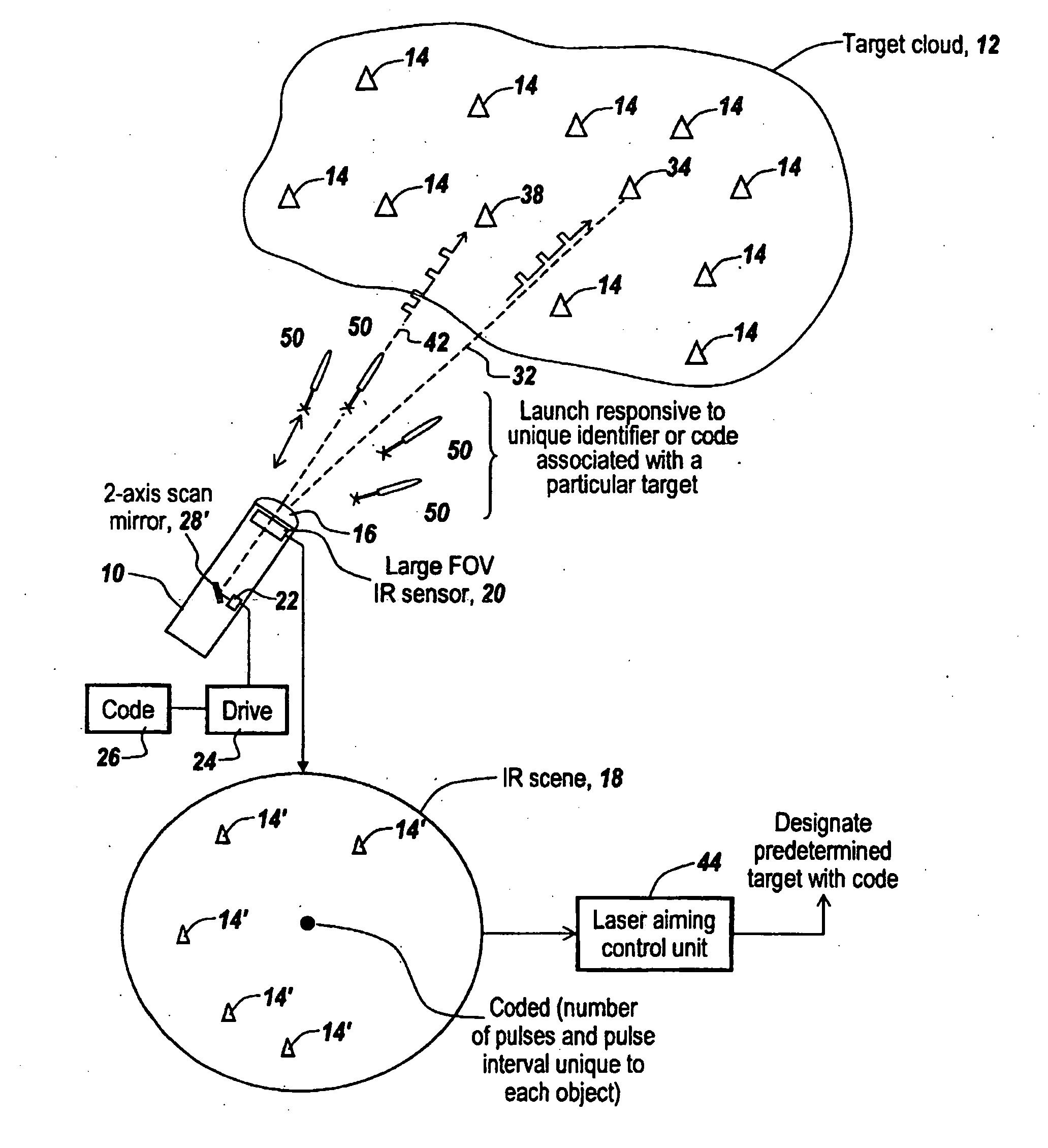
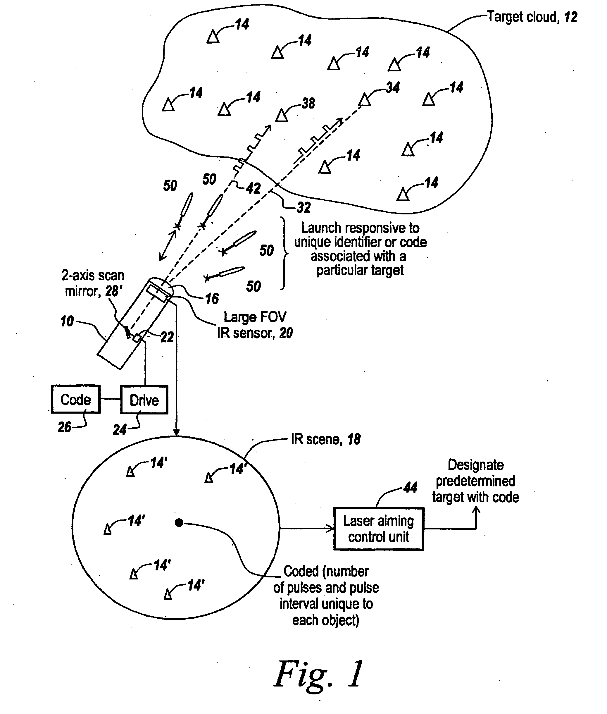
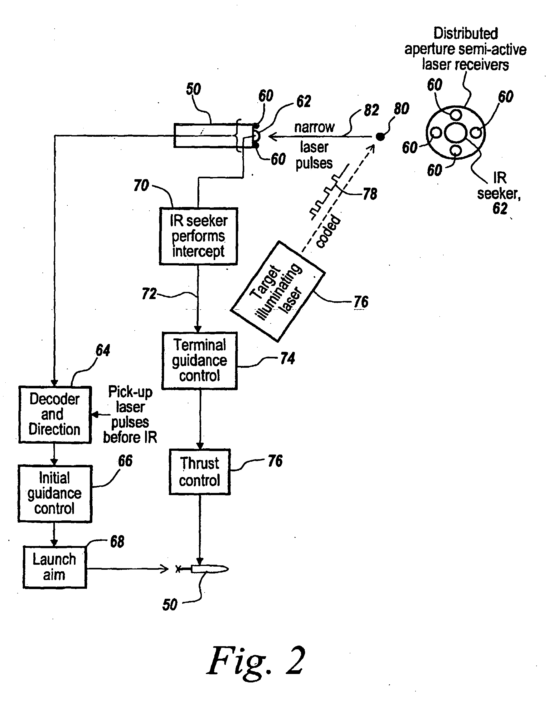
[0015]Rather than employing an all-IR system for determining the position of objects within a target cloud that includes both armed re-entry vehicles and penetration aids such as decoys and chaff, the subject system promotes initially accurate ballistic aiming by providing a laser target designator aboard the carrier vehicle to sequentially sweep the objects of the target cloud and label them. This occurs at a substantial distance from the point at which the kill vehicle guidance system is handed off to its IR heat seeker. Thus a scanning laser target designator is employed in the carrier vehicle that initially detects the location of targets from a large aperture infrared detector and points a laser beam at the detected targets. Thereafter each of the detected targets is sequentially painted with an identifying pulse code, such that light reflected from a target arrives back at the kill vehicle with a code designating the corresponding object in the target cloud.

Problems solved by technology

While in the past projected solutions have included the use of nuclear weapons in space, the obvious disadvantage is the production of radiation.
Moreover, rejected solutions include providing conventional explosives aboard a kill vehicle, with proximity fuses to detonate in the vicinity of a re-entry vehicle.
The reason that this approach has been rejected is that insufficient energy is available to assure the destruction of the re-entry vehicle and the precise timing required to be effective given the large closing velocity.
However, this type of ICBM countermeasure is ineffectual when decoys or multiple warheads are involved.
The problem with a total infrared solution is first and foremost that the objects themselves are only detectable from 10 to 30 kilometers away for small aperture, low cost IR sensors.
Because of the relatively short range of the IR detectors, these midcourse corrections can only be made when the kill vehicle is relatively close to its intended target.
Late-in-the-game midcourse corrections require the expenditure of a considerable amount of fuel for the thrusters on the miniature kill vehicles that in turn limits payload size or the number of kill vehicles carried by the carrier vehicle.
Moreover, utilizing a total IR system, it is virtually impossible to hand off a very complex series of objects to a set of interceptors and to know that one has a one-to-one correlation.
This means that it is difficult to hand off one particular object to one particular interceptor or kill vehicle.
The inability to provide a one-to-one correlation between kill vehicles and objects means that a unacceptable number of kill vehicles will miss a particular object because they are directed to the wrong target.
The problem with multiple targets is that one usually wants to assign one kill vehicle to a target.
Of course, for high-valued targets in a target cloud, there is also the problem of directing multiple kill vehicles to the very high-valued target.
Currently available discrimination software and algorithms can determine or prioritize objects in the target cloud, but the discrimination is never perfect.
Thus one can never determine to a substantial likelihood that the object is an armed re-entry vehicle as opposed to a decoy.
Thus, how to get the kill vehicle aimed at the right target is the essential challenge.

Method used


Image

  • Method and Apparatus for Efficiently Targeting Multiple Re-Entry Vehicles with Multiple Kill Vehicles
  • Method and Apparatus for Efficiently Targeting Multiple Re-Entry Vehicles with Multiple Kill Vehicles
  • Method and Apparatus for Efficiently Targeting Multiple Re-Entry Vehicles with Multiple Kill Vehicles

Examples


Embodiment Construction

[0047]Before describing the figures, it will be appreciated that, when faced with as many as 50 objects in a target cloud, there is a question as to how many traditional heat-seeking kill vehicles can reliably kill an armed re-entry vehicle. If the number of objects in a cloud is relatively few, then traditional heat seekers can effectively guide the corresponding kill vehicle to impact the object. However, as the number of objects increases, there is an exponential decay in performance, resulting in a substantial amount of miscuing.

[0048]Note that the penetration aids utilized by intercontinental ballistic missiles are used to purposely confuse the defenses targeting them, which gives rise to the need for multiple interceptors. Current deployments of exo-atmospheric kill systems employ only one interceptor, which gives rise to the necessity of developing a reliable and effective multiple kill vehicle system.

[0049]As will be appreciated, IR heat seekers can start picking up targets,...


PUM


Abstract

A method and apparatus is provided for increasing the effectiveness of destroying selected objects in a target cloud by prioritizing the objects detected in a large aperture IR detector aboard a carrier vehicle and sequentially illuminating the detected targets with coded laser radiation, followed by the launching of multiple miniature kill vehicles from the carrier vehicle, with each kill vehicle assigned to a differently-coded object in the target cloud due to the reflection back of the coded returns, thus to permit directing of individual miniature kill vehicles to a specific object in the target cloud prior to a handoff to an IR heat seeker in the miniature kill vehicle, actuated to guide the kill vehicle for a final kill.

Description

RELATED APPLICATIONS[0001]This Application claims rights under 35 USC § 119(e) from U.S. application Ser. No. 60 / 604,314 filed Aug. 25, 2004, the contents of which are incorporated herein by reference. This application is related to the following U.S. patent applications, the contents of which are incorporated herein by reference: Ser. No. 09 / 907,148 filed Jul. 17, 2001; Ser. No. 10 / 327,610 filed Dec. 20, 2002, now U.S. Pat. No. 6,909,267; Ser. No. 10 / 334,826 filed Dec. 31, 2002, now U.S. Pat. No. 6,864,965; Ser. No. 10 / 334,884 filed Dec. 31, 2002, now U.S. Pat. No. 6,877,691; Ser. No. 10 / 335,088 filed Dec. 31, 2002, now U.S. Pat. No. 6,870,358; Ser. No. 10 / 400,261 filed Mar. 28, 2003; Ser. No. 10 / 627,186 filed Jul. 25, 2003; and Ser. No. 10 / 627,961 dated Jul. 25, 2003.FIELD OF THE INVENTION[0002]This invention relates to ordnance and more particularly to the guidance of multiple kill vehicles towards targets within a target cloud that include one or more re-entry vehicles and penet...

Claims


Application Information

Patent Timeline
Patent Type & Authority Applications(United States)
IPC IPC(8): F41G11/00
CPCF41H11/02F42B12/58F41G3/145F41G7/008F41G7/308F41G7/2233F41G7/2253F41G7/226F41G7/2293F41G7/2206
Inventor DEFLUMERE, MICHAEL E.VENUTI, RICHARD J.FARIA, FERNANDO M.
Owner BAE SYST INFORMATION & ELECTRONICS SYST INTERGRATION INC
Why Eureka
Try Eureka