
Display apparatus and method for driving display panel thereof

Active Publication Date: 2009-01-01
NOVATEK MICROELECTRONICS CORP
View PDF6 Cites 8 Cited by
  • Summary
  • Abstract
  • Description
  • Claims
  • Application Information

AI Technical Summary

Benefits of technology

[0009]The present invention is directed to a display apparatus, which can provide double frame rate, and effectively eliminate motion blur.
[0010]The present invention is also directed to a method for driving a display panel, which can provide double frame rate, and effectively eliminate motion blur.
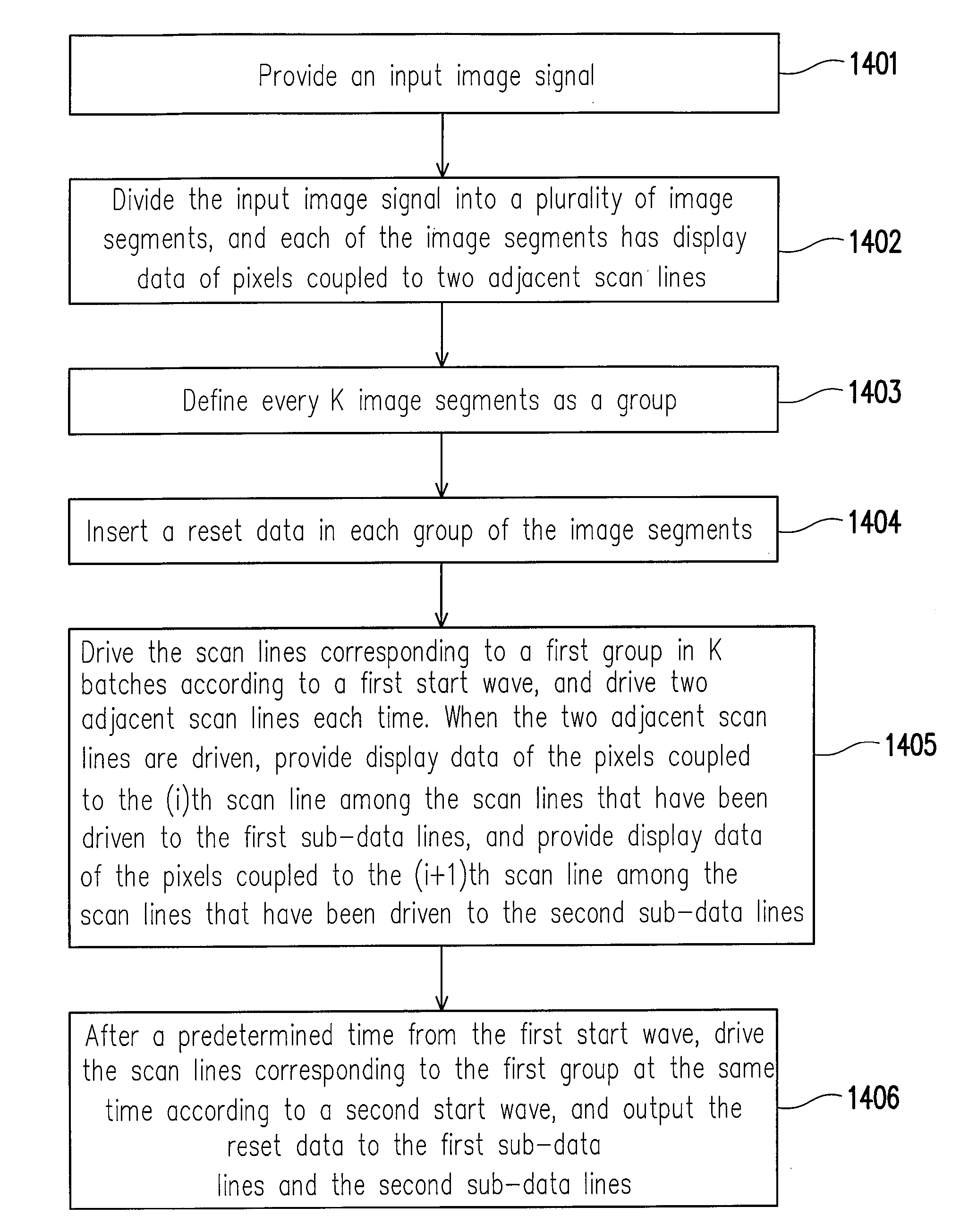
[0018]The present invention adopts a special display panel, in which each column of the data line includes two sub-data lines. Moreover, in the present invention, an input image signal is divided into a plurality of image segments, and each of the image segments has display data of pixels coupled to two adjacent scan lines. Every K image segments are defined as a group. Then, an image signal is formed by inserting a reset data in each group of image segments. Thereafter, display data of a first group are written in K batches according to a first start wave. After a predetermined time from the first start wave, the scan lines corresponding to the first group are driven at the same time according to a second start wave, and the reset data is output to the first sub-data lines and the second sub-data lines. Thus, the present invention can provide double frame rate, and can effectively eliminate motion blur. In addition, as the polarities of the sub-data lines do not change in a frame, the present invention can reset the data of the pixels of several adjacent scan lines at the same time.

Problems solved by technology

Even if the charging time of the image data is extended, the charging time of the reset signal will be insufficient, which results in ineffective charging, and the target value of the reset signal cannot be obtained.
Therefore, the performance of the analog impulse type display will be degraded, and the problem of motion blur cannot be solved effectively.

Method used


Image

  • Display apparatus and method for driving display panel thereof
  • Display apparatus and method for driving display panel thereof
  • Display apparatus and method for driving display panel thereof

Examples


Embodiment Construction

[0035]FIG. 3 shows a display apparatus according to an embodiment of the present invention. The display apparatus includes an arithmetic unit 301, a data reorganization unit 302, a timing controller 303, and a display panel 304. The operations of the above components will be briefly described as follows. The arithmetic unit 301 generates a reset data RD according to an input image signal DATA1 and a counting relation that is related to a plurality of image segments (which will be described later). The reset data RD may be a black or a white image data, or an image data of any single grayscale. The data reorganization unit 302 receives the input image signal DATA1 and the reset data RD, and reorganizes the input signal DATA1 and the reset data RD, so as to generate an image signal DATA2. The timing controller 303 receives the image signal DATA2, so as to generate a plurality of control signals CS according to the image signal DATA2. Moreover, the timing controller 303 sends the plura...


PUM


Abstract

A display apparatus and a method for driving a display panel thereof are provided. Each column of data line in the display panel has tow sub-data lines. The driving method is described as follows. An input image signal is divided into a plurality of image segments, and each of the image segments has display data of pixels coupled to two adjacent scan lines. Every K image segments are defined as a group. An image signal is formed by inserting a reset data in each group of image segments. Display data of a first group are written in K batches according to a first start wave. After a predetermined time from the first start wave, the scan lines corresponding to the first group are driven at the same time according to a second start wave, and the reset data is output to the first sub-data lines and the second sub-data lines.

Description

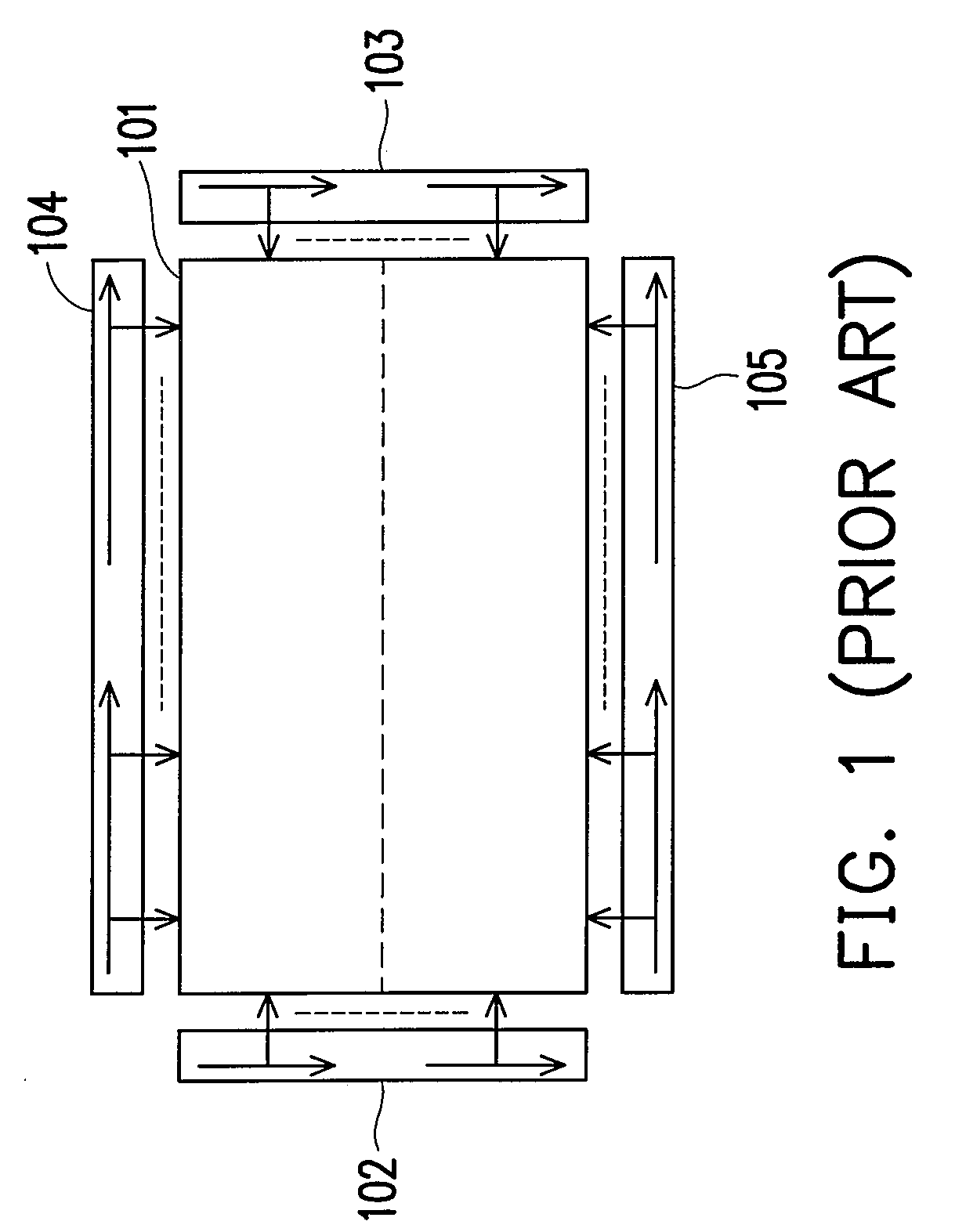
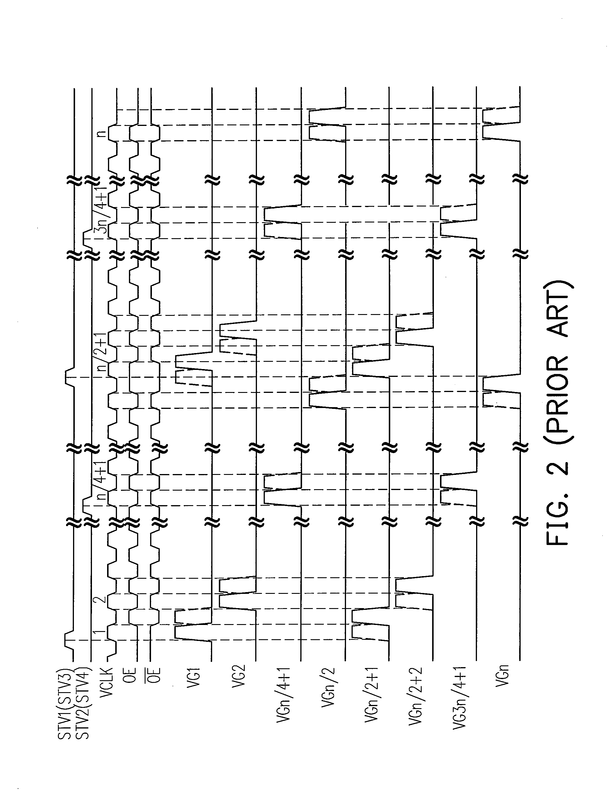
CROSS-REFERENCE TO RELATED APPLICATION[0001]This application claims the priority benefit of Taiwan application serial no. 96123780, filed Jun. 29, 2007. All disclosure of the Taiwan application is incorporated herein by reference.BACKGROUND OF THE INVENTION[0002]1. Field of the Invention[0003]The present invention relates to a display apparatus and a method for driving a display panel thereof. More particularly, the present invention relates to an LCD display apparatus and a method for driving a display panel thereof.[0004]2. Description of Related Art[0005]In order to satisfy the demands for display quality of LCD TV market, liquid crystal display panels are developed gradually towards specifications of high resolution, impulse systems, and high frame rates. However, the above specifications will influence charging time which is already at the margin, and the details are described as follows.[0006]FIG. 1 is a schematic view of the architecture of a conventional display system of do...

Claims


Application Information

Patent Timeline
IPC IPC(8): G09G5/00
CPCG09G3/3614G09G3/3666G09G2320/0261G09G2310/08G09G2310/061
Inventor PAI, FENG-TING
Owner NOVATEK MICROELECTRONICS CORP
Learn More