
Image processing apparatus and method, and image pickup apparatus

Inactive Publication Date: 2012-03-13
PLUG POWER +1
View PDF14 Cites 9 Cited by
  • Summary
  • Abstract
  • Description
  • Claims
  • Application Information

AI Technical Summary

Benefits of technology

[0006]The present invention has been made in view of the above-described background. Accordingly, it is an object of the present invention to make it possible to eliminate motion blur contained in a blurred image.
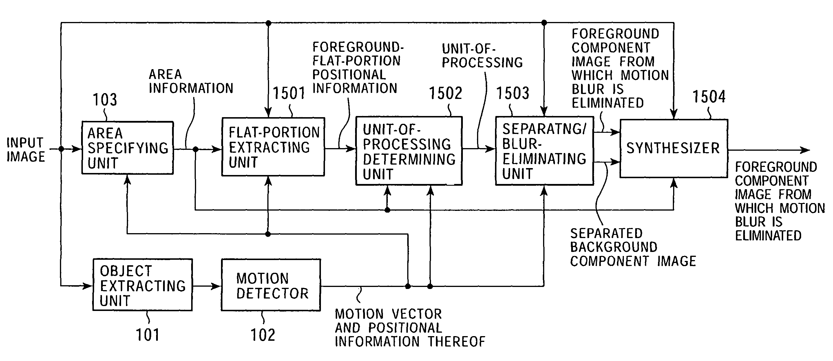
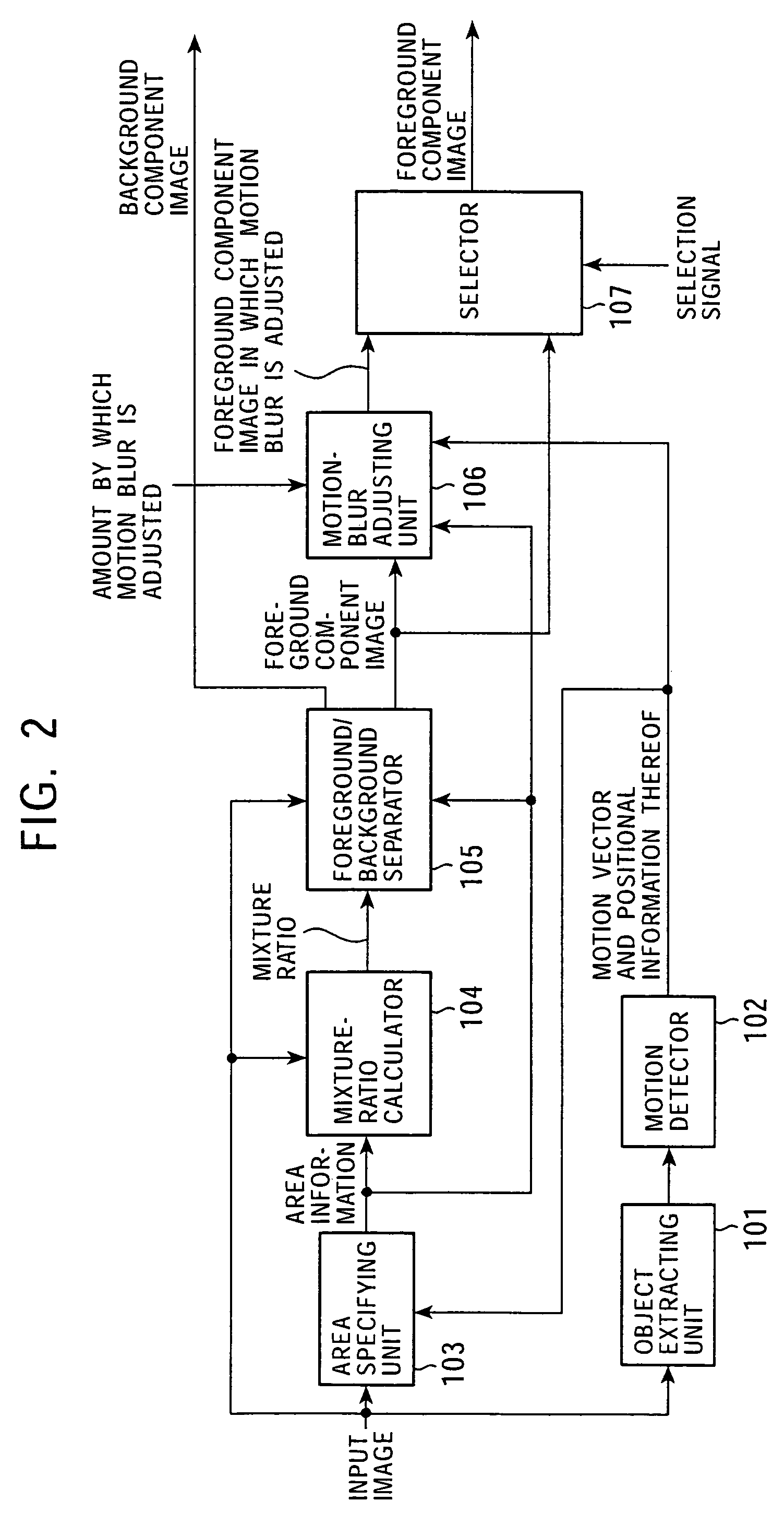
[0007]A first image processing apparatus of the present invention includes: area specifying means for specifying a non-mixed area formed of a foreground area consisting of foreground object components which form a foreground object of image data and a background area consisting of background object components which form a background object of the image data, or a mixed area in which the foreground object components and the background object components area mixed; and processing execution means for simultaneously performing, based on a result obtained by specifying the area by the area specifying means, processing for separating the foreground object components and the background object components from pixel data of the mixed area, and processing for eliminating motion blur from the separated foreground object components.
[0008]The image processing apparatus may further include equal-portion detection means for detecting an equal portion consisting of adjacent pixel data of the foreground area whose values are substantially equal to each other. The processing execution means may simultaneously perform at least the processing for separating the foreground object components and the background object components from the pixel data of the mixed area and the processing for eliminating motion blur from the separated foreground object components based on the detected equal portion and the result obtained by specifying the area by the area specifying means.

Problems solved by technology

Accordingly, there is a problem in which blurred images cannot be corrected to obtain sharp images.

Method used


Image

  • Image processing apparatus and method, and image pickup apparatus
  • Image processing apparatus and method, and image pickup apparatus
  • Image processing apparatus and method, and image pickup apparatus

Examples


Embodiment Construction

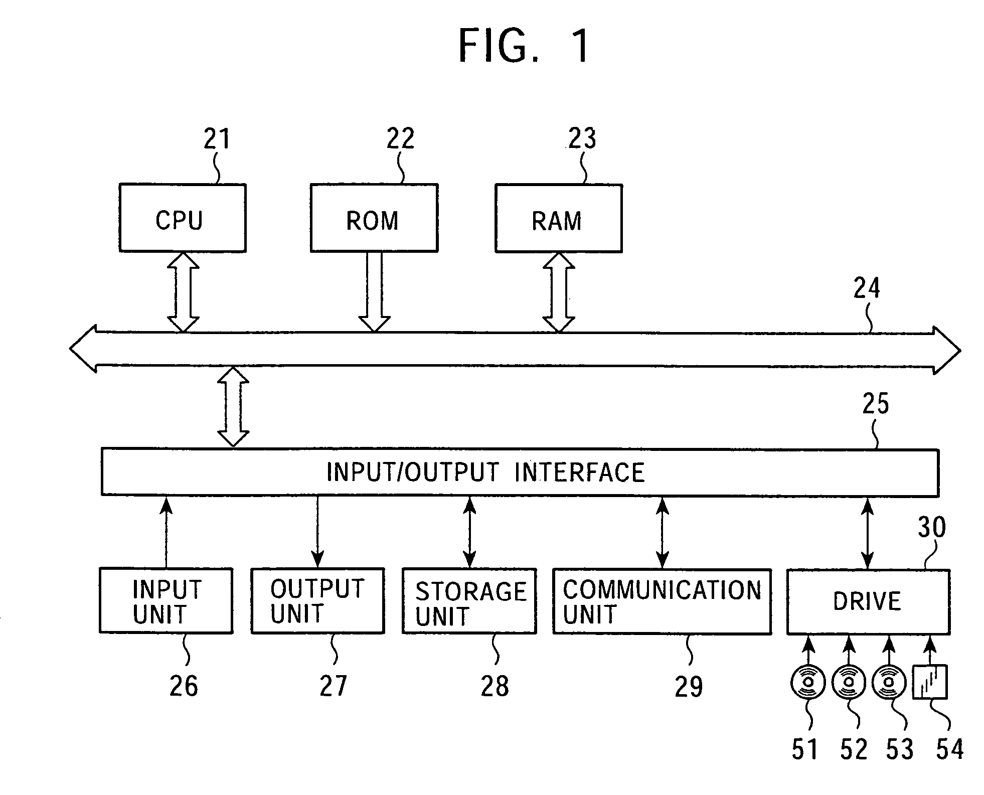
[0256]FIG. 1 is a block diagram illustrating the configuration of an embodiment of a signal processing apparatus according to the present invention. A CPU (Central Processing Unit) 21 executes various types of processing according to programs stored in a ROM (Read Only Memory) 22 or in a storage unit 28. Programs executed by the CPU 21 and data are stored in a RAM (Random Access Memory) 23 as required. The CPU 21, the ROM 22, and the RAM 23 are connected to each other by a bus 24.

[0257]An input / output interface 25 is also connected to the CPU 21 via the bus 24. An input unit 26, which is formed of a video camera, a keyboard, a mouse, a microphone, and so on, and an output unit 27, which is formed of a display, a speaker, and so on, are connected to the input / output interface 25. The CPU 21 executes various types of processing in response to a command input from the input unit 26. The CPU 21 then outputs an image or sound obtained as a result of the processing to the output unit 27.

[...


PUM


Abstract

The present invention particularly relates to an image processing apparatus in which motion blur contained in a blurred image can be eliminated. An area specifying unit 103 specifies a non-mixed area formed of a foreground area consisting of foreground object components which form a foreground object and a background area consisting of background object components which form a background object, or a mixed area in which the foreground object components and the background object components are mixed. A separating / blur-eliminating unit 1503 simultaneously performs processing for separating the foreground object components and the background object components from the pixel data of the mixed area and processing for eliminating motion blur from the separated foreground object components based on a result obtained by specifying the area. The present invention is applicable to an image processing apparatus in which a difference between a signal detected by an image-capturing device and the real world is considered.

Description

TECHNICAL FIELD[0001]The present invention relates to image processing apparatuses, and more particularly, to an image processing apparatus in which a difference between a signal detected by a sensor and the real world is taken into consideration.BACKGROUND ART[0002]A technique for detecting incidents occurring in the real world by a sensor and for processing sampled data output from the image sensor is widely used.[0003]For example, motion blur occurs in an image obtained by capturing an object moving in front of a predetermined stationary background with a video camera if the moving speed is relatively high.[0004]Hitherto, in order to prevent such motion blur, for example, the speed of an electronic shutter is increased so as to decrease the exposure time.[0005]However, in the method in which the shutter speed is increased, it is necessary to adjust the shutter speed of a video camera before capturing an image. Accordingly, there is a problem in which blurred images cannot be corr...

Claims


Application Information

Patent Timeline
IPC IPC(8): H04N5/262H04N5/228G06K9/40G06K9/00G06T5/00G06T7/20
CPCG06T7/20G06T5/003G06T2207/10016G06T2207/20144G06T2207/20012G06T2207/20201G06T7/194G06T5/73
Inventor KONDO, TETSUJIROSAWAO, TAKASHIISHIBASHII, JUNICHINAGANO, TAKAHIROFUJIWARA, NAOKIMIYAKE, TORUWADA, SEIJI
Owner PLUG POWER
Learn More