
Transfer device and image forming apparatus including same

Inactive Publication Date: 2009-01-01
RICOH KK
View PDF6 Cites 9 Cited by
  • Summary
  • Abstract
  • Description
  • Claims
  • Application Information

AI Technical Summary

Benefits of technology

[0015]Exemplary aspects of the present invention provide a transfer device that can reduce a color shift in a composite color image due to relative displacements of write start positions between multiple image carriers and due to speed fluctuation of a belt member.

Problems solved by technology

In such a tandem electrophotographic image forming apparatus, a change in temperature of optical components such as lens and mirrors of a writing unit can cause fluctuations in optical paths of light, where even a slight fluctuation of optical paths can lead to relative displacement of write start positions between image carriers.
When the writing unit starts writing respective latent images while the latent images are relatively out of registration, improperly formed single-color toner images are sequentially transferred onto the belt member or the recording medium, and as a result, a defective full-color image having a color shifted from its original image position is produced.
However, there is another factor contributing to misregistration of the single-color toner images, which is fluctuation in drive speed of a belt member that can be caused by, for example, uneven thickness of the belt member in a direction of movement of the belt member, eccentricity of a drive roller driving the belt member, etc.
Consequently, the speed fluctuation of a belt member during a transfer operation can result in misregistration between images, even though the relative positions between the single-color toner images on the image carriers are properly arranged.
More specifically, registration error of respective single-color toner images caused by fluctuation in the speed of the belt member cannot be eliminated by adjustment of the latent image write start timing and / or adjustment of inclination of the optical components.
By contrast, misregistration caused by fluctuation in the speed of the belt member varies the relative positions of dots in each single-color toner image between colors, and therefore adjustments of the latent image write start timing and / or of inclination of the optical components cannot eliminate the misregistration.
When the speed fluctuation of the belt member occurs while the optical sensors are detecting pattern images for misregistration detection, the pattern images of different colors cannot be detected properly.
The above-described problems have also occurred in image forming apparatuses employing a multi-cycle electrophotographic printing scheme, in which a belt member rotates more than one time while transferring, per cycle, each visible image formed on an image carrier onto a surface of the belt member or a recording medium carried by the belt member.

Method used


Image

  • Transfer device and image forming apparatus including same
  • Transfer device and image forming apparatus including same
  • Transfer device and image forming apparatus including same

Examples


Embodiment Construction

[0040]In describing preferred embodiments illustrated in the drawings, specific terminology is employed for the sake of clarity. However, the disclosure of this present invention is not intended to be limited to the specific terminology so selected and it is to be understood that each specific element includes all technical equivalents that operate in a similar manner.

[0041]Referring now to the drawings, wherein like reference numerals designate identical or corresponding parts throughout the several views, preferred embodiments of the present invention are described.

[0042]Referring now to the drawings, wherein like reference numerals designate identical or corresponding parts throughout the several views, preferred embodiments of the present invention are described.

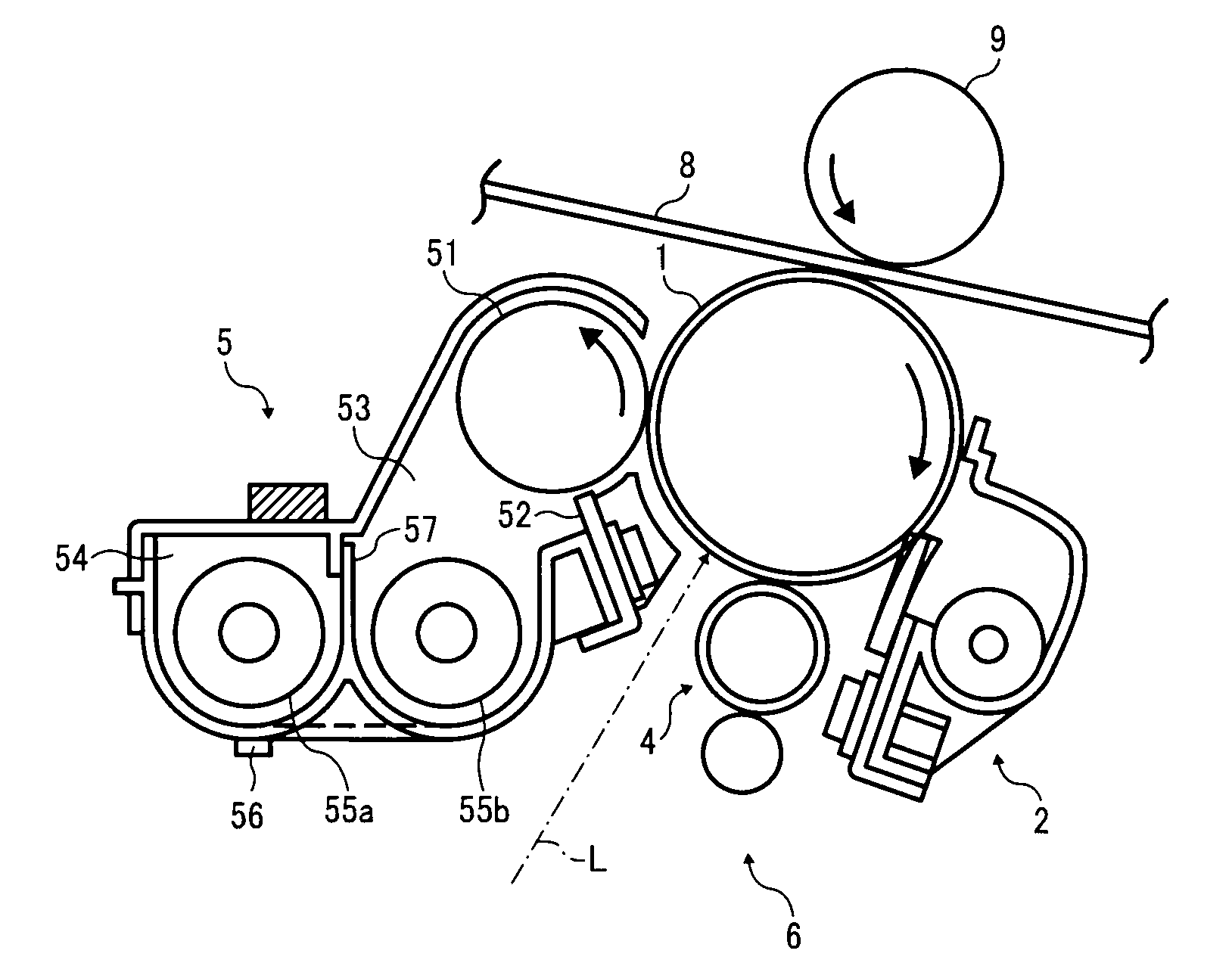
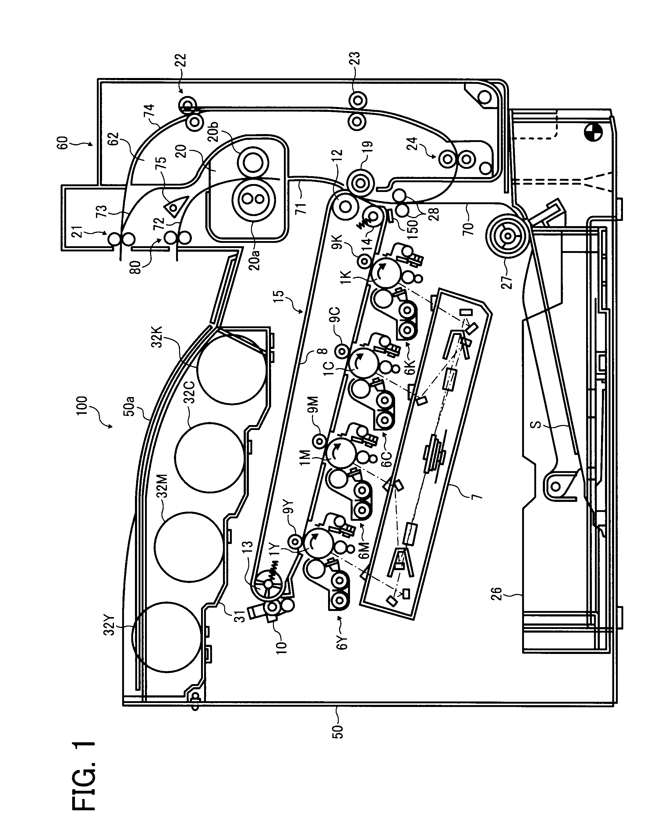
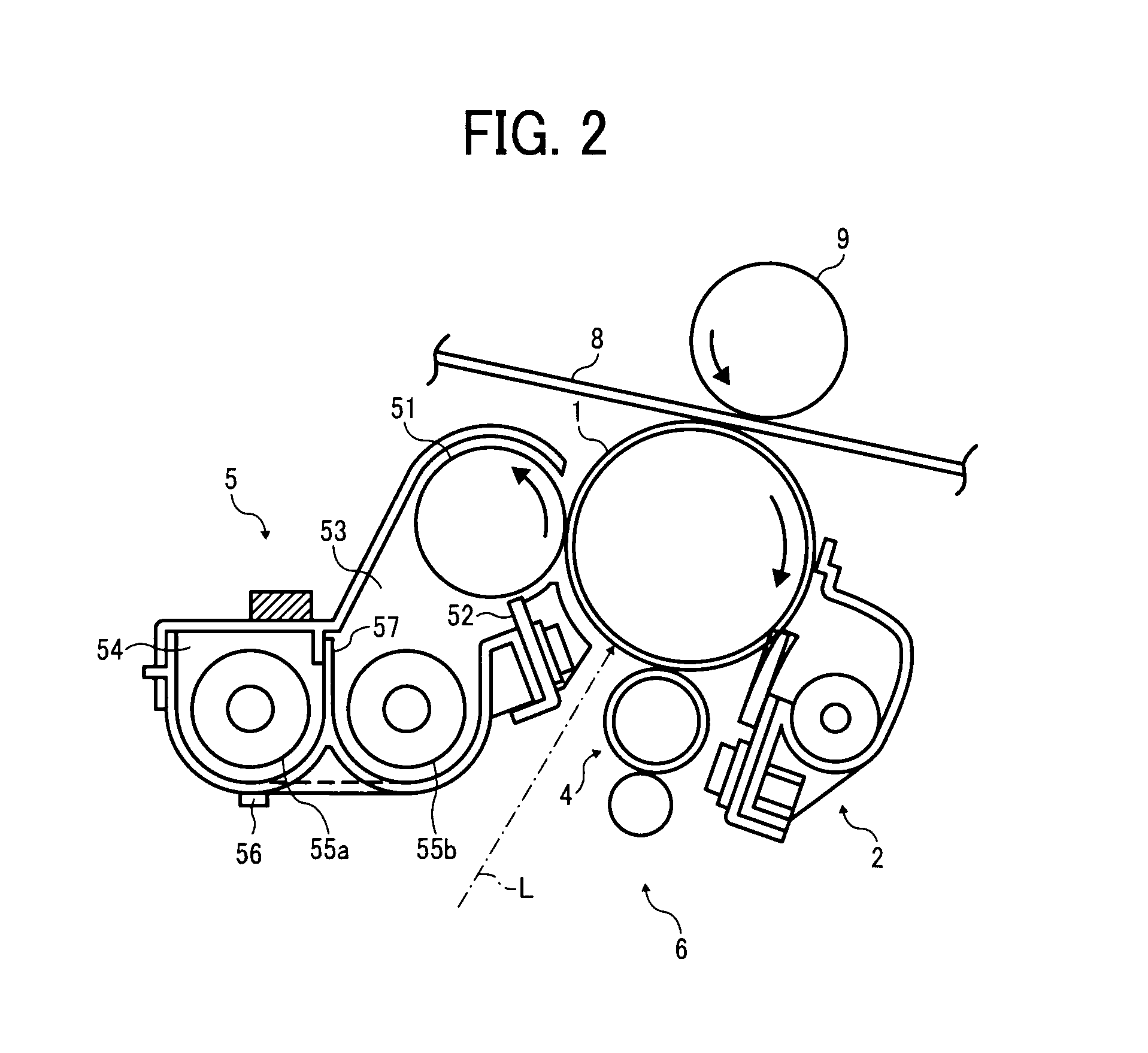
[0043]Referring to FIGS. 1 and 2, a schematic configuration of a printer 100 serving as an electrophotographic image forming apparatus according to an exemplary embodiment of the present invention is described.

[0044]The ...


PUM


Abstract

A transfer device, which transfers an image onto a recording medium directly or indirectly and is included in an image forming apparatus, includes an endless belt member extended between a drive roller rotated and a driven roller and configured to receive the image from the image carrier part onto either a surface thereof or the recording medium carried on the surface thereof while moving according to rotations of the drive roller, and a rotation speed detector configured to detect a rotation speed of the driven roller. An image detector is provided either to the transfer device or to the image forming apparatus to detect the image formed on the endless belt member directly or the recording medium carried on the endless belt member, and disposed facing the driven roller in a circumferential direction of the endless belt member.

Description

CROSS-REFERENCE TO RELATED APPLICATIONS[0001]The present patent application claims priority under 35 U.S.C. §119 from Japanese Patent Application No. 2007-167804, filed on Jun. 26, 2007 in the Japan Patent Office, the contents and disclosure of which are hereby incorporated by reference herein in their entirety.BACKGROUND OF THE INVENTION[0002]1. Field of the Invention[0003]Exemplary embodiments of the present invention generally relate to a transfer device and an image forming apparatus including the transfer device, and more particularly, to a transfer device including an endless belt to transfer a visible image formed on each of multiple image carriers onto either an endless belt member or a recording medium carried on a surface of the endless belt member to generate a composite toner image, and an image forming apparatus for forming images using the transfer device.[0004]2. Discussion of the Related Art[0005]Image forming apparatuses employing a tandem electrophotographic method...

Claims


Application Information

Patent Timeline
IPC IPC(8): G03G15/16
CPCG03G2215/00059G03G2215/0158G03G15/1615G03G15/0131G03G15/5058
Inventor YAMAGUCHI, TOSHITAKASAEKI, KAZUCHIKAFURUYA, MASAHARUSEKINE, TAKUYA
Owner RICOH KK
Learn More