Configurable Bone Fixation System

a bone fixation system and a technology of fixed bones, applied in the field of fixed bone fixation systems, can solve the problems of not being able to move relatively of components, and achieve the effect of reducing the number of components and reducing the number of parts

Inactive Publication Date: 2009-01-08
DALL DESMOND MEIRING +1
View PDF12 Cites 43 Cited by
  • Summary
  • Abstract
  • Description
  • Claims
  • Application Information

AI Technical Summary

Benefits of technology

[0010]The mode of connection may also allow some length adjustment.

Problems solved by technology

(It is not generally desirable for the components to undergo relative movement after the surgical procedure has been completed.)

Method used


Image

  • Configurable Bone Fixation System
  • Configurable Bone Fixation System
  • Configurable Bone Fixation System

Examples


Embodiment Construction

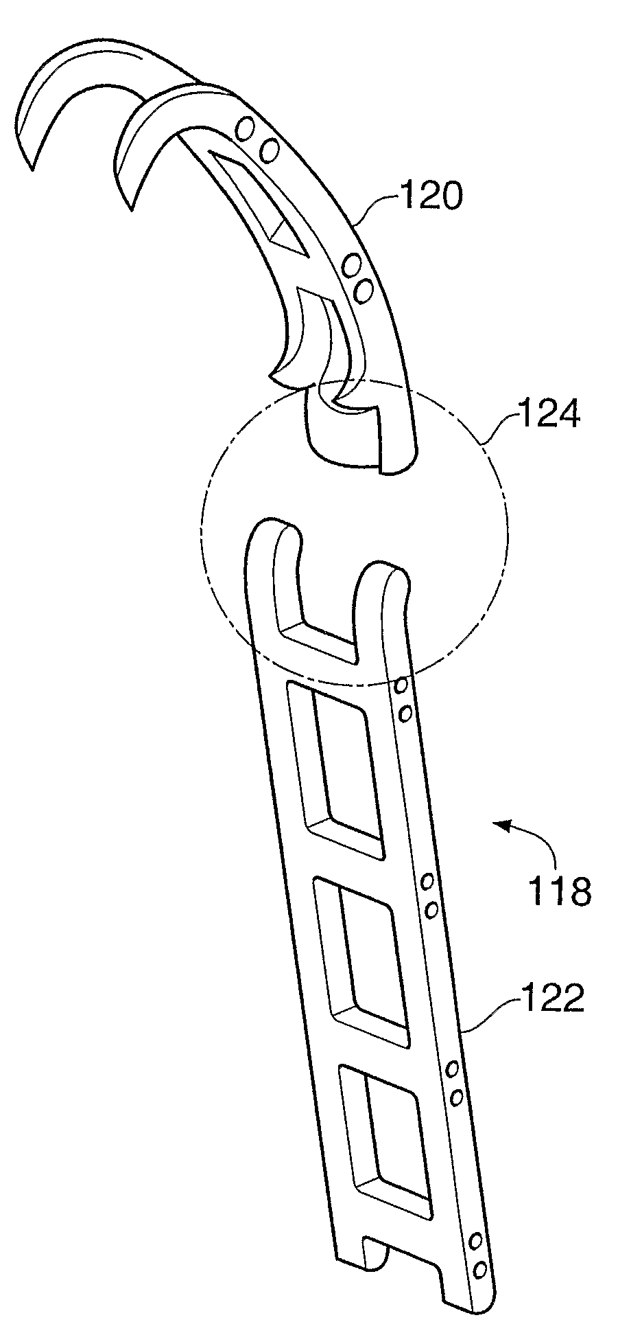
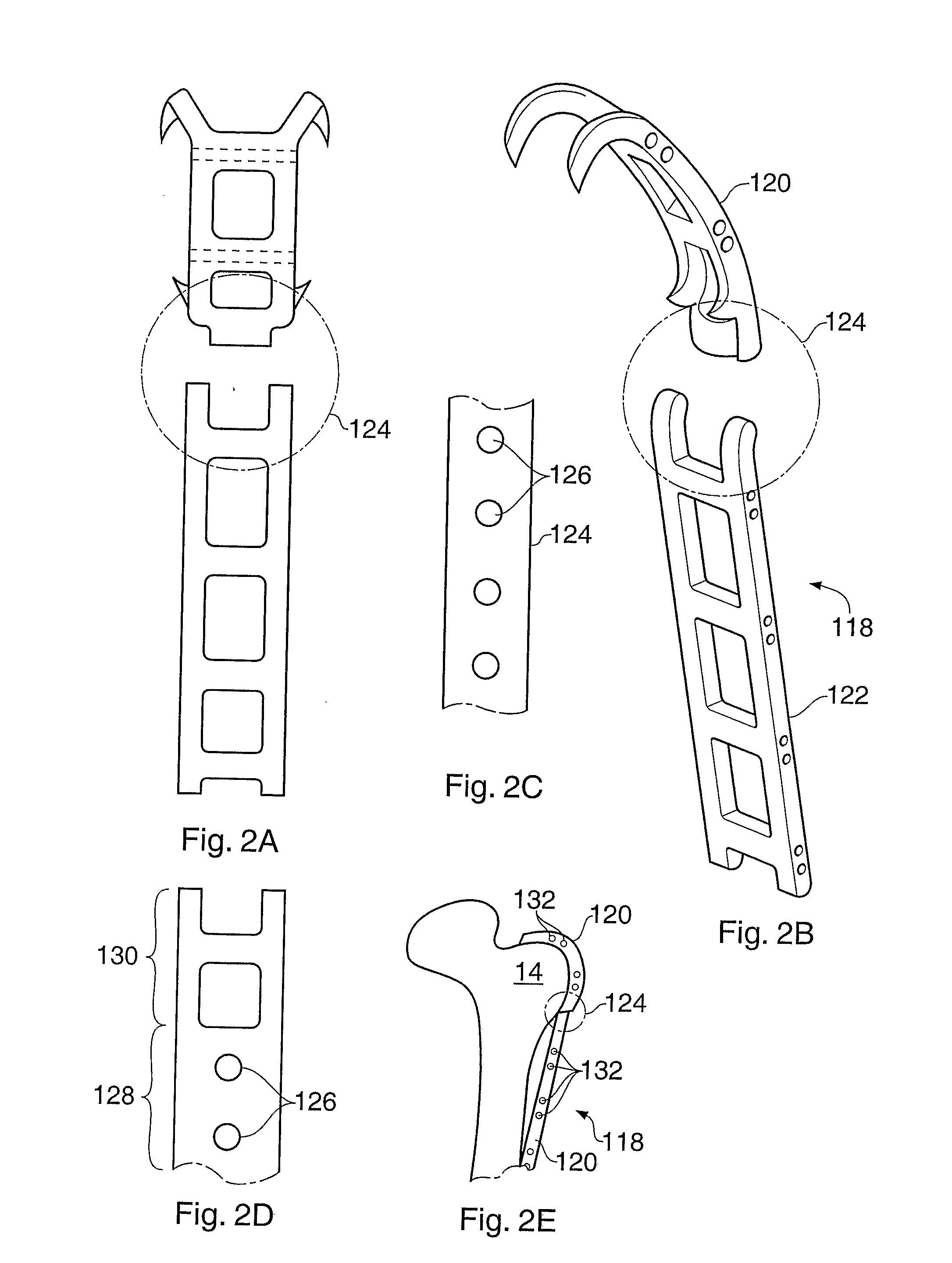
[0036]As shown schematically in FIGS. 2A and 2B, the solution proposed in the present application is to produce a grip plate 118 in which the grip portion 120 is connected to the plate portion 122 via a junction 124 which allows the grip portion to be reoriented relative to the plate portion, prior to fixation to the bone, so that the positions of both portions on the bone can be optimised. This is referred to hereafter as a “flexible junction”. This does not necessarily mean that flexing is possible after fixation, which is generally undesirable. This “flexible junction” is shown in FIGS. 2A and 2B merely by a chain-dotted circle.

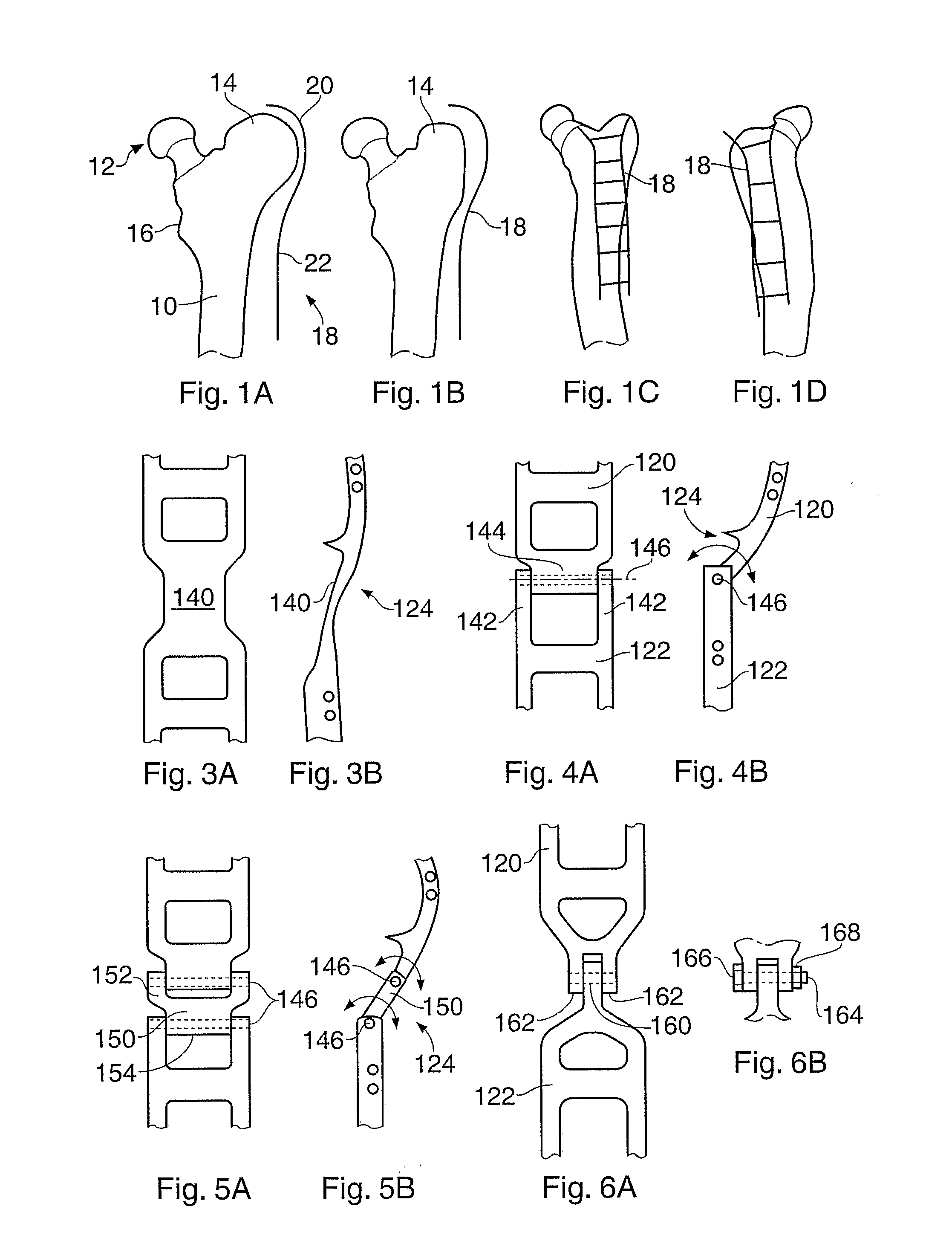
[0037]In FIGS. 2A and 2B, the plate portion 122 has the form of a “ladder plate” as disclosed in patent U.S. Pat. No. 5,665,089 (incorporated herein by reference). The plate portion can take other forms, e.g. any of those disclosed in U.S. Pat. No. 5,665,089. It can be simple plate 124 with screw holes 126 as shown in FIG. 2C, or a combination having a por...


PUM


Abstract

A bone fixation system has an elongate portion (122; 299) for engaging over a long bone (e.g. a femur) and an end engagement portion (120; 260) for engaging over an end region of a long bone (e.g. a greater trochanter). To allow for variation in bone geometries, the two portions are pivotably connectable. Preferably the connection is lockable. Thus the system can be adapted to a particular bone geometry and then made rigid.

Description

TECHNICAL FIELD[0001]The present invention relates to a configurable bone fixation system, namely to surgical apparatus and methods for use in the treatment of bones and joints. It is particularly, though not exclusively, concerned with systems for use in hip replacement operations such as attachment of trochanter and / or proximal femur reconstruction, revision hip surgery or when an extended or Wagner osteotomy approach is used. It is also relevant to other anatomical regions, particularly regions involving a long bone and an end region thereof. For example, it has application to the proximal tibia, distal femur, and the proximal and distal humerus regions.BACKGROUND ART[0002]The present inventors have previously devised many components of use to surgeons. For example, U.S. Pat. Nos. 4,269,180 and 6,066,141 describe bone grips. These are curved hook-like elements, primarily for engaging over a part of a greater trochanter which has been cut (osteotomised) and temporarily removed dur...

Claims


Application Information

Patent Timeline
Patent Type & Authority Applications(United States)
IPC IPC(8): A61B17/70A61B17/56A61B17/74A61B17/80A61B17/82
CPCA61B17/748A61B17/82A61B17/809A61B17/8085A61B17/80
Inventor DALL, DESMOND MEIRINGMILES, ANTHONY WILLIAM
Owner DALL DESMOND MEIRING
Why Eureka
Try Eureka