Methods and systems for material fixation

a technology of material fixation and methods, applied in the field of devices, systems and methods for material fixation, can solve the problems of difficulty in achieving the effect of achieving the effect of reducing the difficulty of traditional techniques used to fix tendon to bone, reducing the difficulty of traditional techniques, and improving the quality of traditional methods

Active Publication Date: 2008-07-31
CAYENNE MEDICAL INC
View PDF99 Cites 211 Cited by
  • Summary
  • Abstract
  • Description
  • Claims
  • Application Information

AI Technical Summary

Benefits of technology

[0021]More particularly, there is provided in one aspect of the invention a material fixation system, which comprises an implant which is placeable in a tunnel disposed in a portion of bone, wherein the tunnel is defined by walls comprised of bone. A first member is deployable outwardly to engage the tunnel walls for anchoring the implant in place in the tunnel, and a second member is deployable outwardly to engage tissue material to be fixed within the tunnel. The second member also functions to move the tissue material outwardly into contact with the tunnel walls. A third member forming a part of the implant is movable to deploy the first member outwardly. A fourth member is provided actuating the third member to move in order to deploy the first member.
[0022]Preferably, the fourth member comprises a portion which functions to deploy the second member outwardly. The implant comprises a body having a distal end and a proximal end, and the first member is disposed on the body. The first member comprises an arm which is pivotally attached to the body. The third member comprises a wedge which is movable generally axially to deploy the arm.
[0023]In one presently preferred embodiment, the fourth member comprises a deployment screw having a distal end and a proximal end, wherein the deployment screw is adapted to extend axially through the body. The distal end of the deployment screw has a threaded portion which is engageable with a complementary threaded portion on the wedge, wherein rotation of the deployment screw causes relative movement of the deployment screw and the wedge. The wedge moves proximally to depl...

Problems solved by technology

In addition, tendons which are torn from their insertion site into bone also frequently require repair.
Traditional techniques that are used to fix tendon to bone suffer from a number of limitations as a result of the methodology used, including the use of a “keyhole” tenodesis, pull-out sutures, bone tunnels, and interference screw fixation.
This technique is challenging as it is often difficult to sculpt the keyhole site and insert the tendon into the tunnel.
In addition, if the tendon knot unravels in the postoperative period, the tendon will slide out of the keyhole, losing fixation.
This technique has lost favor in recent years due to a host of associated complications, which include wound problems, weak fixation strength, and potential injury to adjacent structures.
The creation of bone tunnels is relatively complicated, often requiring an extensive exposure to identify the margins of the tunnels.
This tedious process is time-consuming and fraught with complications, which include poor tunnel placement and fracture of the overlying bone bridge.
Graft isometry, which is easy to determine with single point fixation, is difficult to achieve because the tendon exits the bone from two points.
This portion of the procedure is often time-consuming and frustrating to a surgeon.
Finally, the procedure can be compromised if the bone bridge above the tunnel breaks, resulting in loss of fixation.
The technique restricts fixation to the strength of the sutures, and does not provide any direct tendon to bone compression.
While this technique eliminates the need for secondary incisions to place the post, the fixation strength is limited to suture strength alone.
This technique does not provide direct tendon to bone compression; as such this technique may slow healing and lead to graft tunnel widening due to the “bungee effect” and “windshield wiper effect”.
As a result, this technique has limited clinical applications and is used primarily for salvage when bone tunnels break or backup fixation is important.
Some disadvantages related to soft tissue interference screws are that they can be difficult to use, and can also cut or compromise the tendon during implantation.
While this screw system provides advantages in the insertion of tendon into bone in cases when a pull through stitch is not available, it is still limited by the potential for tendon rotation or disruption as the screw compresses the tendon.
The surgical technique is also complicated, typically requiring two or mo...

Method used


Image

  • Methods and systems for material fixation
  • Methods and systems for material fixation
  • Methods and systems for material fixation

Examples


embodiment 110

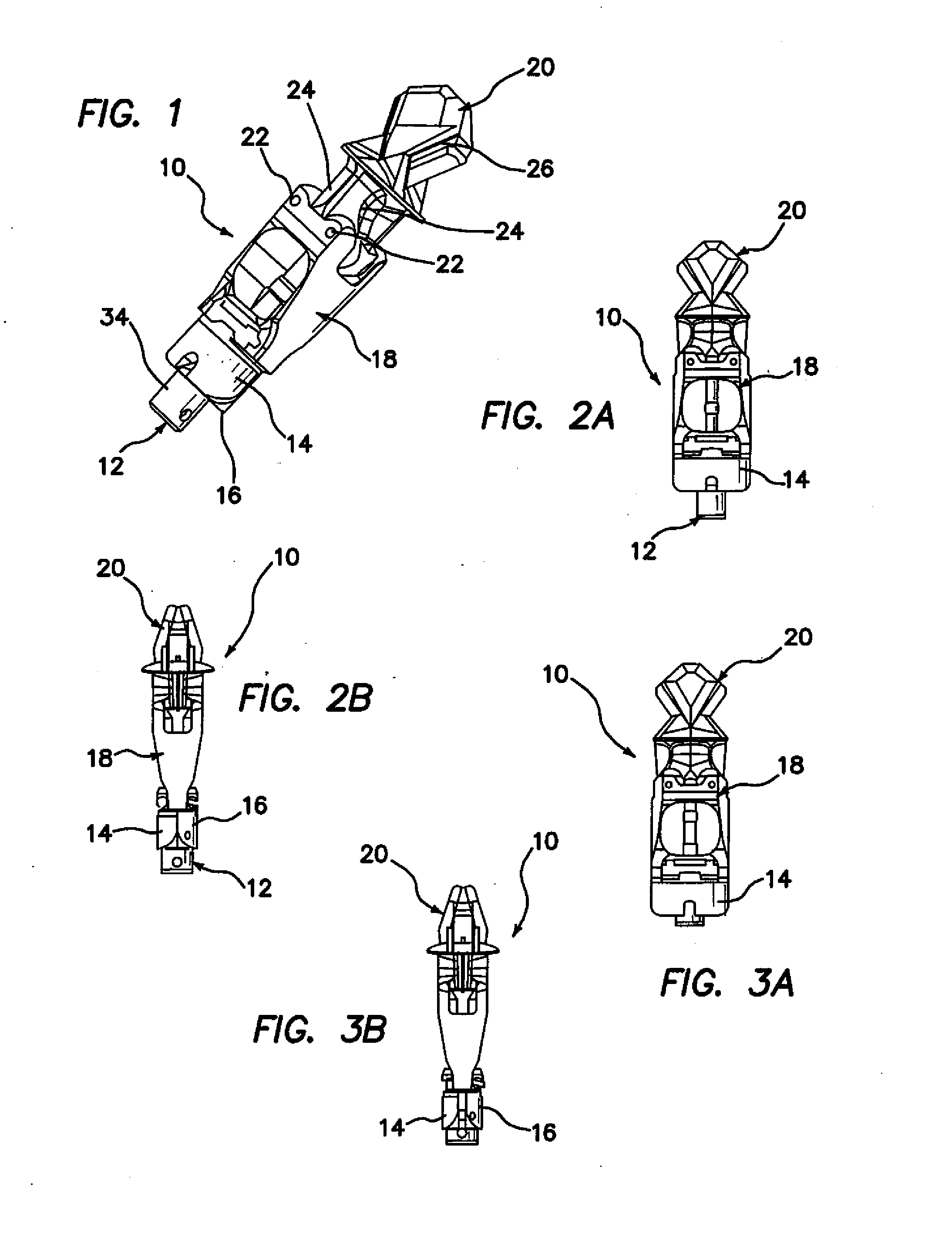
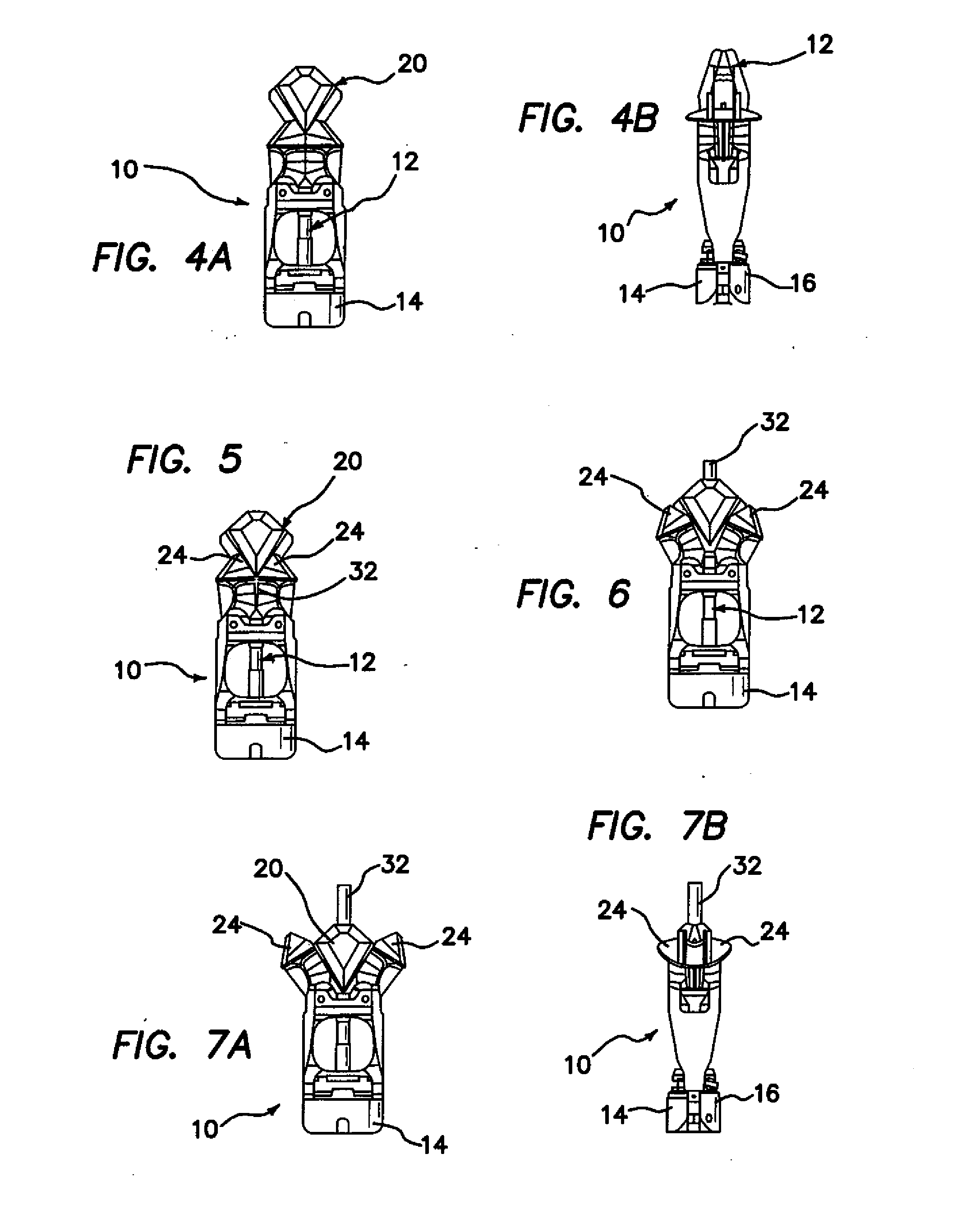
[0104]In FIGS. 18-21 there is shown another implant embodiment 110, wherein like elements are identified with like reference numerals as for the embodiment of FIGS. 1-14, preceded by the numeral 1. As shown, the deployment screw 112 protrudes through the compression pads 114 and 116, which are each integrated into the body 118. The deployment screw 112 is threaded at its distal end into the wedge 120. Two pins 122 attach a pair of arms 124 to the body 118, as shown.

[0105]As noted above, in this embodiment the compression pads 114, 116 are integrated into the body 118. This feature permits the use of a shorter implant than is the case for the implant of FIG. 1. A track 126 in the wedge 120 attaches to track posts 128 on the arms 124 (FIG. 29), which keep the wedge 120 from rotating during deployment. The compression pads expand as the implant is deployed. In particular, the screw 112 expands the pads 114, 116 outwardly by siding on a compression taper 72 (FIG. 27), as shown in FIGS. ...

embodiment 210

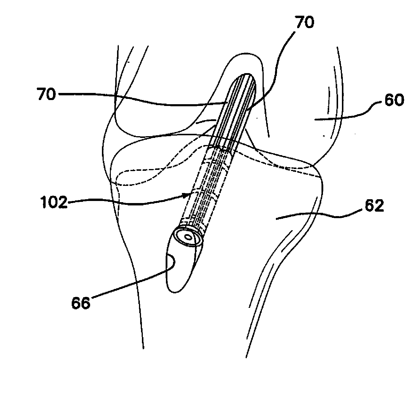
[0113]Still another embodiment of the inventive implant is illustrated in FIGS. 33-54, wherein like elements to those of the prior embodiments are identified by like reference numerals, preceded by the numeral 2. This embodiment 210 utilizes the cortical bone for fixation in combination with tendon-to-bone compression. In this version of the invention, the deployment screw 212 is offset to one side of the implant 210, for the purpose of permitting easier passing of tendon through the orifice. This implant deploys in two steps. The deployment screw 212 is rotated clockwise as an arm 78 and wedge 220 slide together across tapered faces 80 (FIG. 46) and 82 (FIG. 48) until they lock together with their respective cortical locks 84, 86. The wedge 220 and the arm 78 lock into place by filling a majority of the cross section of the femoral tunnel. Thus, the implant is free to move in the femoral tunnel, allowing tactile feedback to ensure engagement of a cortical tab 88 with the cortex.

[01...


PUM


Abstract

A soft tissue fixation system, most typically applicable to orthopedic joint repairs, such as anterior cruciate ligament (ACL) knee repair procedures, comprises an implant which is placeable in a tunnel disposed in a portion of bone, wherein the tunnel is defined by walls comprised of bone. A first member is deployable outwardly to engage the tunnel walls for anchoring the implant in place in the tunnel, and a second member is deployable outwardly to engage tissue material to be fixed within the tunnel. The second member also functions to move the tissue material outwardly into contact with the tunnel walls to promote tendon-bone fixation. Extra graft length is eliminated by compression of the tendon against the bone at the aperture of the femoral tunnel, which more closely replicates the native ACL and increases graft stiffness. The inventive device provides high fixation of tendon to bone and active tendon-bone compression. Graft strength has been found to be greater than 1,000 N (Newtons), which is desirable for ACL reconstruction systems.

Description

[0001]This application claims the benefit under 35 U.S.C. 119(e) of the filing date of Provisional U.S. Application Ser. No. 60 / 854,178, entitled Methods and Systems for Material Fixation, filed on Oct. 24, 2006, which application is expressly incorporated herein by reference.[0002]This application is also related to co-pending U.S. application Ser. No. 11 / 281,566 entitled Devices, Systems, and Methods for Material Fixation, filed on Nov. 18, 2005 and published as U.S. Patent Application Publication No. US 2006 / 0155287 on Jul. 13, 2006, and to co-pending U.S. application Ser. No. 11 / 725,981, entitled Devices, Systems, and Methods for Material Fixation, filed on Mar. 20, 2007. Both of these prior pending applications are commonly owned and herein expressly incorporated by reference.BACKGROUND OF THE INVENTION[0003]The present invention relates generally to devices, systems and methods for material fixation. More specifically, the present invention relates to a technique that can be u...

Claims


Application Information

Patent Timeline
IPC IPC(8): A61F2/08
CPCA61F2/0811A61F2002/0835A61F2002/0882A61F2002/0858A61F2002/0852A61F2002/0829A61B17/86
Inventor BAIRD, KEVIN N.HARPER, DEREK J.KOVALSKI, JOE P.KOVALSKI, JOANNEMONTGOMERY, KENNETH D.
Owner CAYENNE MEDICAL INC
Why Eureka
Try Eureka