

Bone fixation with a strut-stabilized bone plate
a bone plate and stabilization technology, applied in the field of bone plate fixation with a stabilizing bone plate, can solve the problems of misplaced or misdirected bone screws that fasten the bone plate to the bone, inability to provide a suitable combination of bone plates, and difficulty in fixing the desired alignment of bone fragments with the use of bone plates
- Summary
- Abstract
- Description
- Claims
- Application Information
AI Technical Summary
Benefits of technology
Problems solved by technology
Method used
Image

Examples
example 1
Exemplary System for Strut-Stabilized Bone Fixation
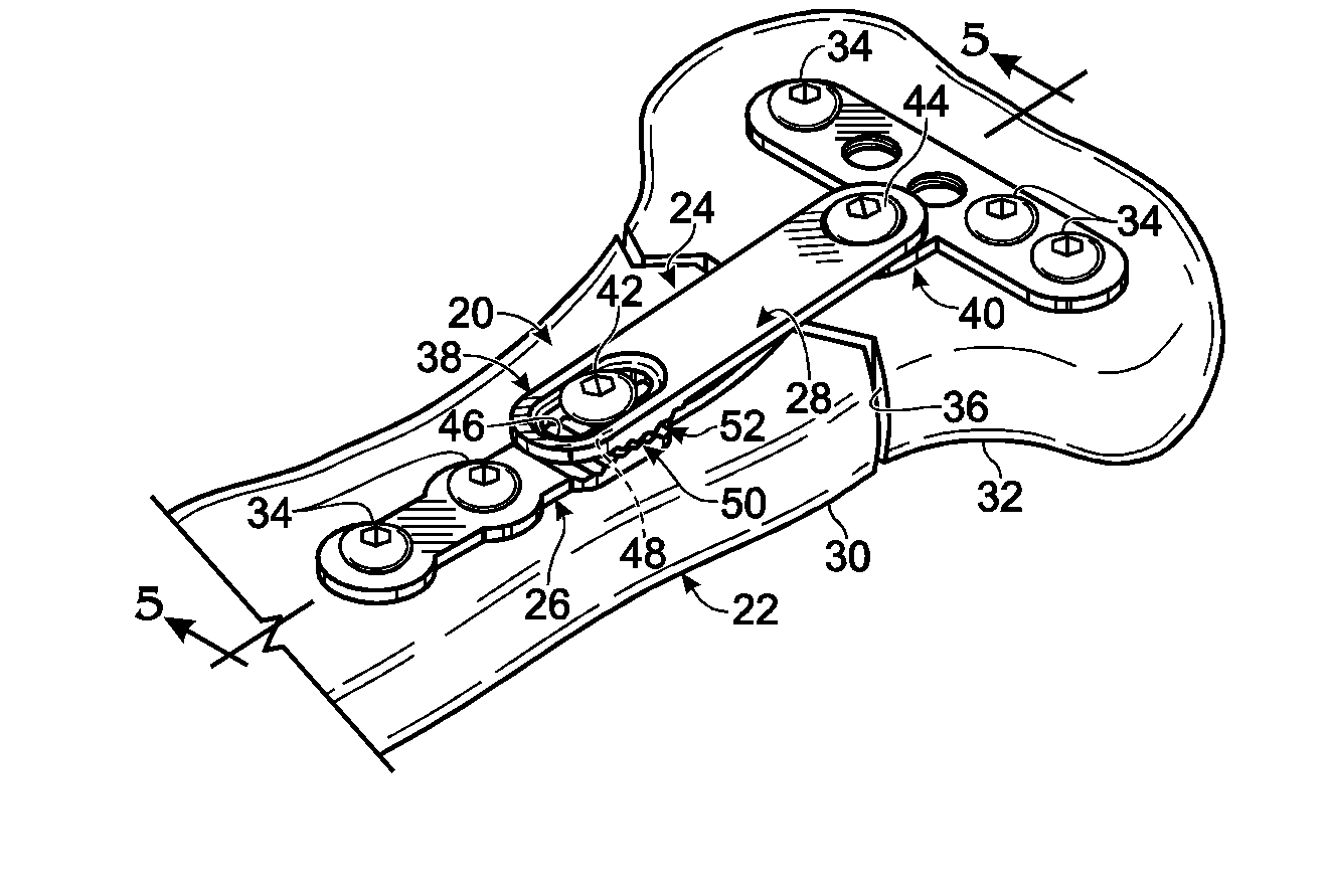
[0055]This example describes selected aspects of an exemplary fixation system 20 for strut-stabilized fixation of bones, particularly stabilization of a distal portion of a radius bone; see FIGS. 2-6. Fixation system 20 was introduced above in Section I, with reference to FIG. 1.
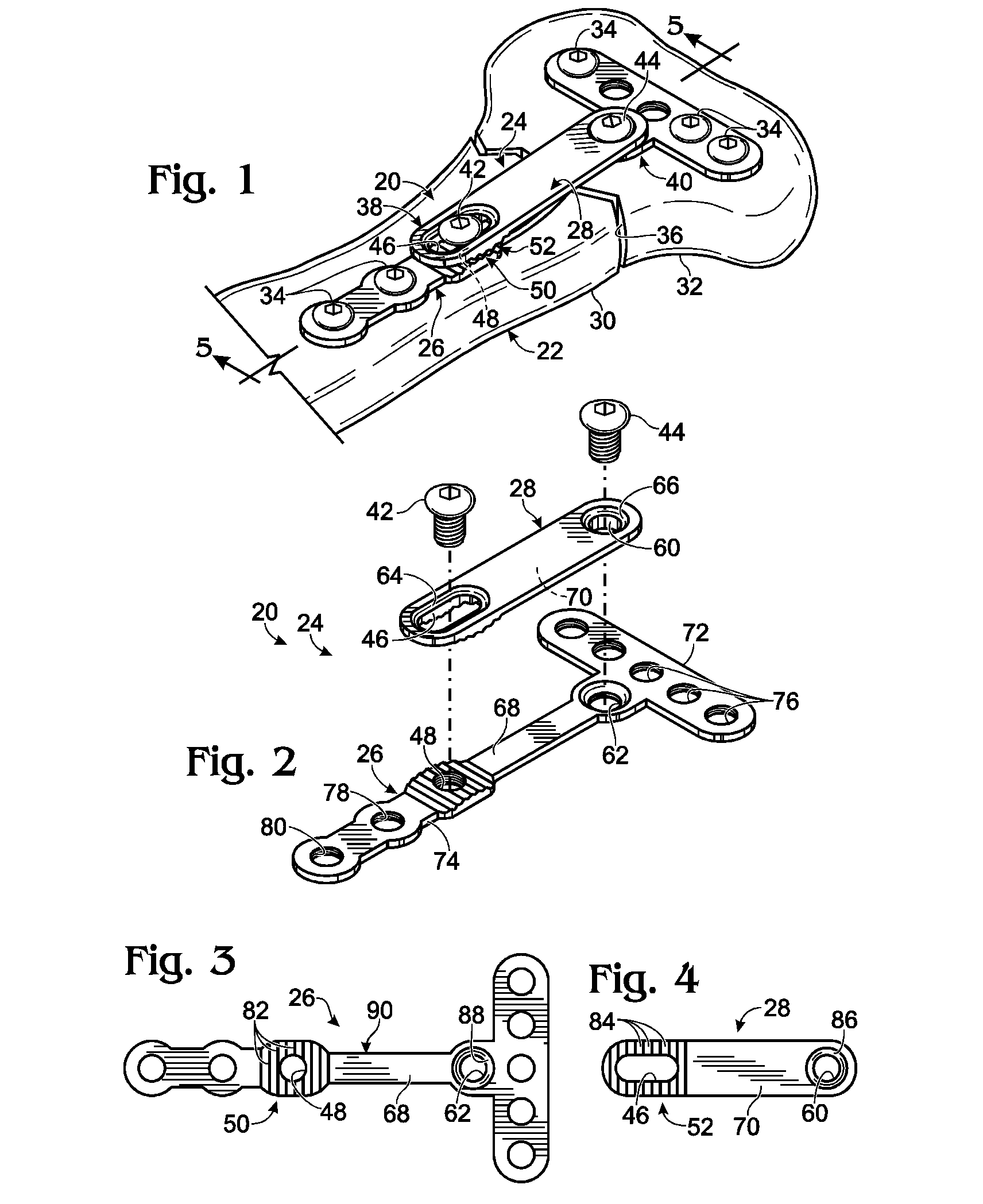
[0056]FIG. 2 shows an exploded view of fixation system 20. Bone plate 26 and strut (or strut plate) 28 may define one or more pairs of elongate and / or non-elongate apertures for receiving fasteners that secure the strut to the bone plate. For example, here, the bone plate and strut define two pairs of aligned apertures: strut 28 defines elongate aperture 46 and a circular aperture 60 that align, respectively, with aperture 48 and aperture 62 of the bone plate.
[0057]Each of apertures 46 and 60 of the strut may have any suitable structure. The strut apertures may be nonthreaded or threaded internally, as appropriate, and may include respective countersinks 64,...
example 2
Exemplary Method of Bone Fixation with a Bone Plate and Strut
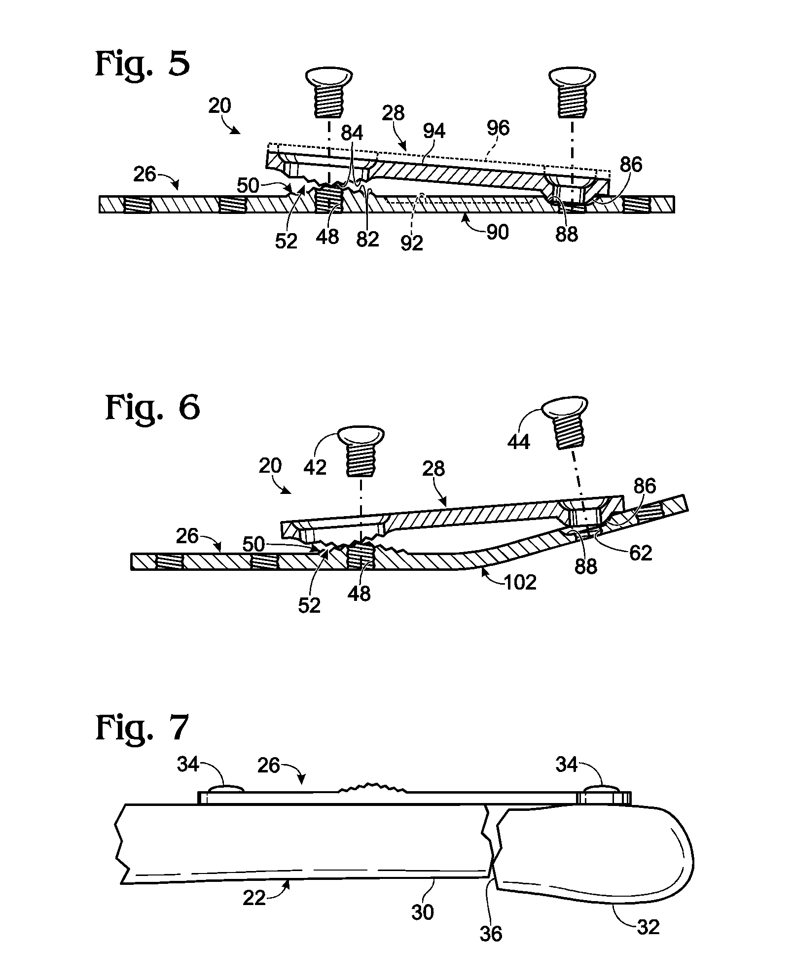
[0068]This example describes an exemplary method of fixing a bone using a fixation device including a bone plate and strut; see FIGS. 7-10. The exemplary method is illustrated here using fixation system 20 (see FIGS. 1-6). However, any other suitable bone plate and strut may be used on any suitable bone having any suitable indication.
[0069]FIG. 7 shows bone plate 26 secured to fractured radius 22 using bone screws 34. The bone plate may span fracture 36 with bone screws placed through openings of the bone plate and into proximal fragment(s) 30 and distal fragment(s) 32 of the fractured radius. The bone plate may be disposed adjacent and / or may abut any suitable surface of the radius, such as a volar or dorsal surface of a distal portion of the radius.
[0070]Any suitable number of bone screws may be placed into bone on opposing sides of a discontinuity in the radius. However, in the present example, at least one bone screw (...
example 3
Selected Embodiments I
[0076]This example describes exemplary features of a strut connected to a bone plate. The strut may include any suitable combination of the following features. The strut may connect between two (or more) regions of the bone plate. The strut may connect within a portion of the footprint of the bone plate. The strut may not connect to bone independent of the bone plate. The strut may not directly contact bone. The strut may substantially overlap a portion of the bone plate. The strut may be aligned with the long axis of bone. The strut may connect to the bone plate on opposite sides of an injury to bone. The strut may connect to the bone plate on opposite sides of a bend in the bone plate (and / or a bending region of the bone plate at which the bone plate is bent selectively to create a bent configuration). At least a central region of the strut may be spaced from the bone plate when connected to the bone plate.
PUM
 Abstract
Description
Claims
Application Information