Bone fixation assembly and method of securement

a technology of bone fixation and bone, applied in the field of spine fixation system, can solve the problems of affecting the function of the involved joint, affecting the healing effect of the affected joint, so as to achieve the effect of reducing the pressure on the inward sid

Inactive Publication Date: 2005-09-20
AESCULAP INC
View PDF90 Cites 202 Cited by
  • Summary
  • Abstract
  • Description
  • Claims
  • Application Information

AI Technical Summary

Benefits of technology

[0010]In a preferred configuration the through passage of the fixation device is provided with an inverted frusto-conical seat and the exterior surface of the bushing is provided with a mating inverted frusto-conical base configured and dimensioned for seating in this seat. The seat and base are coaxial with the central axis of the bushing and through passage. The cam mechanism is comprised of annularly spaced upwardly extending ramp cams on the upper surface of the bushing and inwardly extending overhangs are provided on the through passage above the upper surface of the cams or bushing and this overhang is provided with downwardly facing cam following surfaces that are configured and dimensioned for engaging the ramp cams on the top of the bushing when the bushing is axially rotated in its seat. This rotation causes the bushing to be driven downwardly into its inverted frusto-conical seat by the ramp cams to thereby inwardly compress the bushing bore against the screw head. The cams and cam followers surfaces may also be provided for ridges to prevent back-out of the cams.

Problems solved by technology

This extensive exposure disrupts a considerable amount of tissue, particularly the lumbar paraspinal musculature which needs to be stripped off the vertebra bones for exposure.
This stripping leads to muscle damage directly caused by either electrical cautery or manual cutting or indirectly by interruption of vascular supply to the muscle due to coagulation or cutting of vessels, and caused also by embarrassment of the vascular supply during the course of surgery due to compression by retractors on the muscle which are required to maintain exposure.
In addition, spinal implants can impact upon the facet joints of the spine, particularly the upper most pair of pedicle screws, which can cause pain or dysfunction of the involved joint.
The present day surgical approach therefore has added to patient morbidity due to the extent of the surgical exposure, tissue damage done primarily to the posterior longitudinal musculature of the spine during the exposure, blood loss and risk of infection.
Large open operations also tend to be the cause of significant postoperative pain and disability.
Accordingly, these issues lead to longer hospital stays, higher postoperative complications, such as phlebitis and pneumonia brought on by immobility, and greater consumption of postoperative medications with their resultant side affects.
Also, interference by metal implants of the normal function of the rostral facet joints has been implicated in the early degeneration of these joints, as well as pain and disability, all which could lead to other more involved surgeries.

Method used


Image

  • Bone fixation assembly and method of securement
  • Bone fixation assembly and method of securement
  • Bone fixation assembly and method of securement

Examples


Embodiment Construction

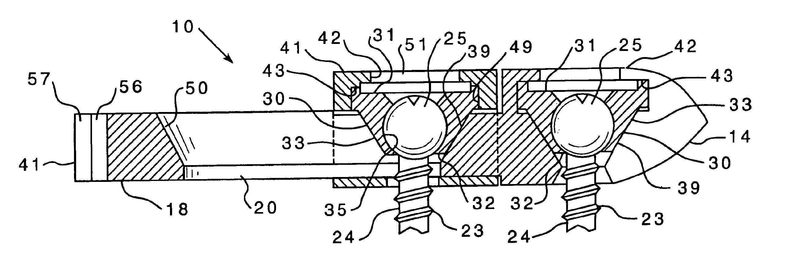
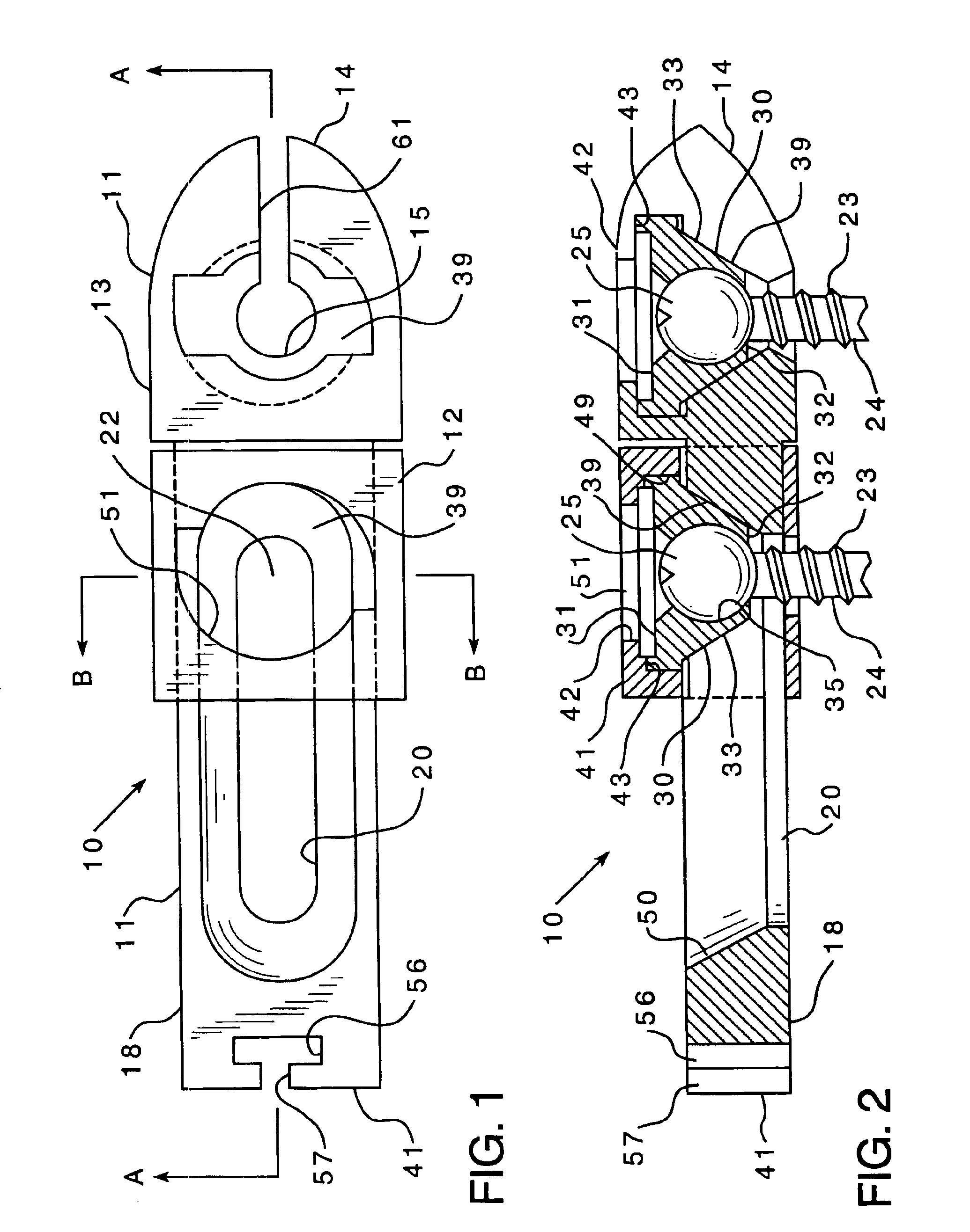
[0020]Referring first to FIGS. 1 and 2, the bone fixation assembly 10 of the present invention is provided for stabilization of the spine and is an improved modification of the implant plate assembly shown and described in the inventor's aforementioned copending application for use in the inventive procedure therein described for minimum invasive surgical implantation of a plate assembly for fixation of the spine. The assembly 10 is comprised of two separate portions, a first portion 11 and a second portion 12 which are adjustably assembled together. The first portion 11 includes a first receiving socket element 13 at the distal end 14 of assembly 10. This first screw receiving socket element 13 is configured with a screw shank through passage 15 for attachment of element 13 to vertebra bone with the aid of a bone fixation screw 23 as seen in FIG. 2. The plan view of FIG. 1 does not include the bone fixation screws and other interior parts which are included in FIG. 2 in order to pr...


PUM


Abstract

A bone plate is provided for fixation of spaced vertebra. The bone plate has at least one through passage for securing the plate to bone with a bone fixation screw. The threaded shaft of a bone fixation screw is inserted through a bushing located in the through passage of the bone plate and the screw is thereby threadably secured to the underlying bone and the bushing is then compressed inward against the head of the screw with cams that are actuated by rotating the bushing in the through passage whereby the screw is locked relative to the bone plate. The bushing is not only compressed inwardly against the head of the screw but is also compressed downwardly by the cams into a seat to clamp separate elements of the bone plate together.

Description

CROSS-REFERENCE[0001]This application is a continuation-in-part of U.S. application Ser. No. 10 / 615,196, filed Jul. 7, 2003, for SPINAL STABILIZATION IMPLANT AND METHOD OF APPLICATION.FIELD OF THE INVENTION[0002]The present invention relates generally to spinal fixation systems. More particularly, the present invention pertains to a spinal plate assembly which includes a mechanism for fixably attaching and locking bone fixation screws to the plate at desired angles and for simultaneously locking otherwise adjustable portions of the plate together.BACKGROUND OF THE INVENTION[0003]Spinal surgery on the lumbar and thoracic spines have classically been open operations, meaning that the instrumentation used is placed through an incision that exposes all of the spine to be instrumented, as well as a portion of spine above and below the area to be instrumented due to the need for proper visualization. This extensive exposure disrupts a considerable amount of tissue, particularly the lumbar...

Claims


Application Information

Patent Timeline
Patent Type & Authority Patents(United States)
IPC IPC(8): A61B17/58A61B17/56A61B17/70A61B17/80A61B17/88
CPCA61B17/7059A61B17/8023A61B17/8047A61B17/56
Inventor DALTON, BRIAN E.
Owner AESCULAP INC
Why Eureka
Try Eureka