Wear Assembly and Lock Mechanism

a technology of wear assembly and lock mechanism, which is applied in the direction of soil shifting machine/dredger, construction, etc., can solve the problems of tedious and difficult task of disassembly of such wear assembly

Active Publication Date: 2013-07-25
CUTTING EDGES REPLACEMENT PARTS
View PDF24 Cites 87 Cited by
  • Summary
  • Abstract
  • Description
  • Claims
  • Application Information

AI Technical Summary

Benefits of technology

[0033]The transverse portion can include a tapered end so that its interaction with said base and wear member, results in movement of said wear member relative to said base as said lock member is being moved to said locked condition.
[0034]The bo...

Problems solved by technology

The disassembly of such wear assemblies tends to be a tedious and difficult task and users are seeking better and mor...

Method used


Image

  • Wear Assembly and Lock Mechanism
  • Wear Assembly and Lock Mechanism
  • Wear Assembly and Lock Mechanism

Examples


Embodiment Construction

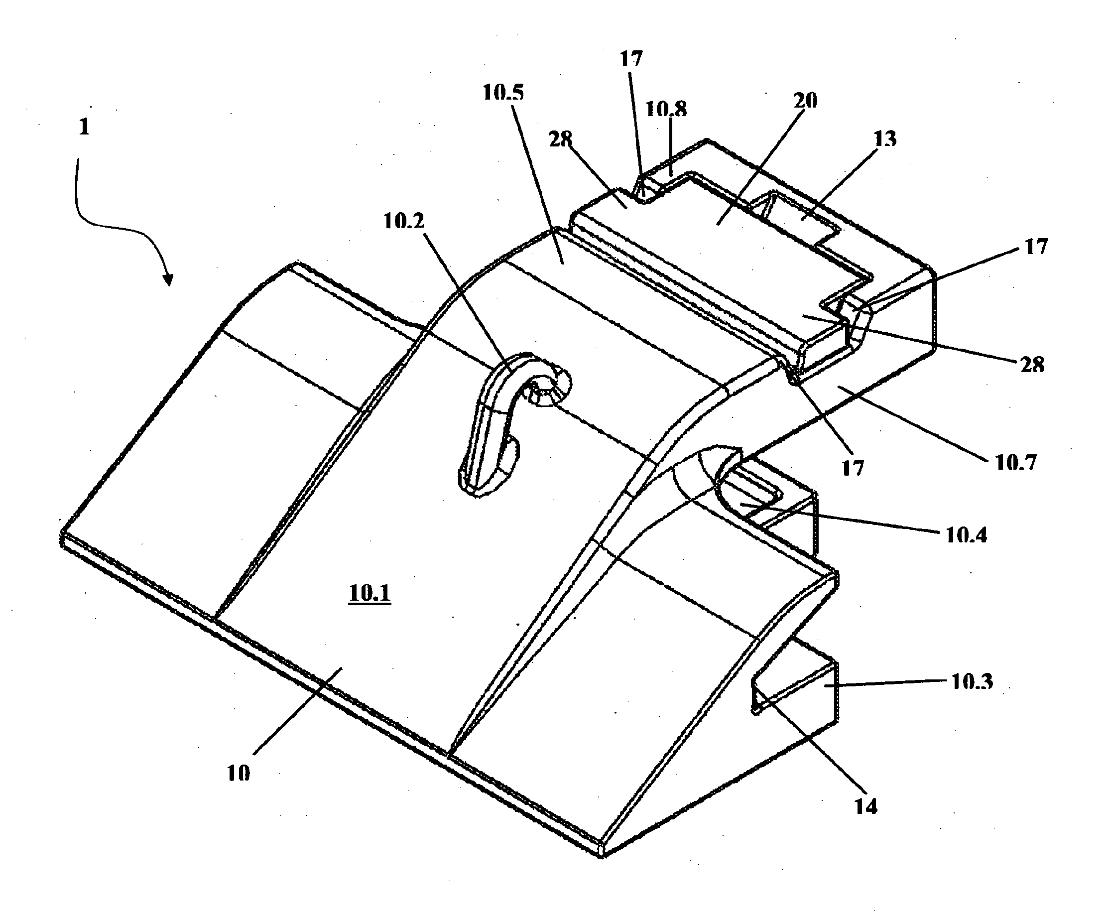
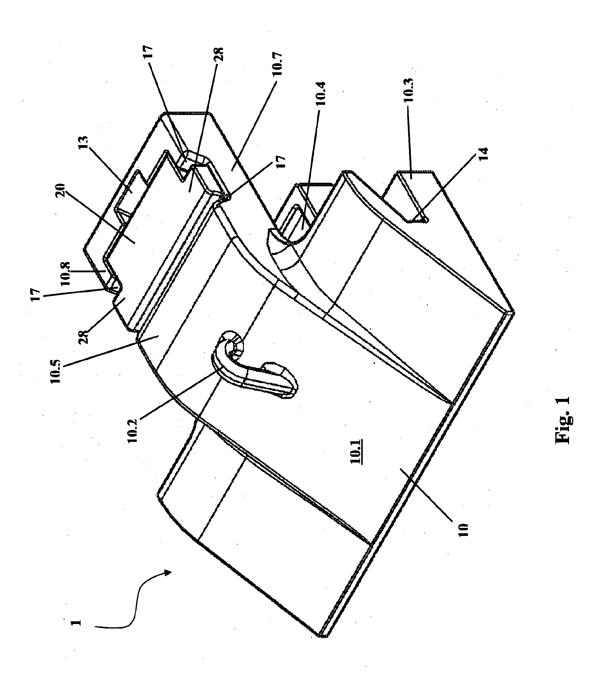
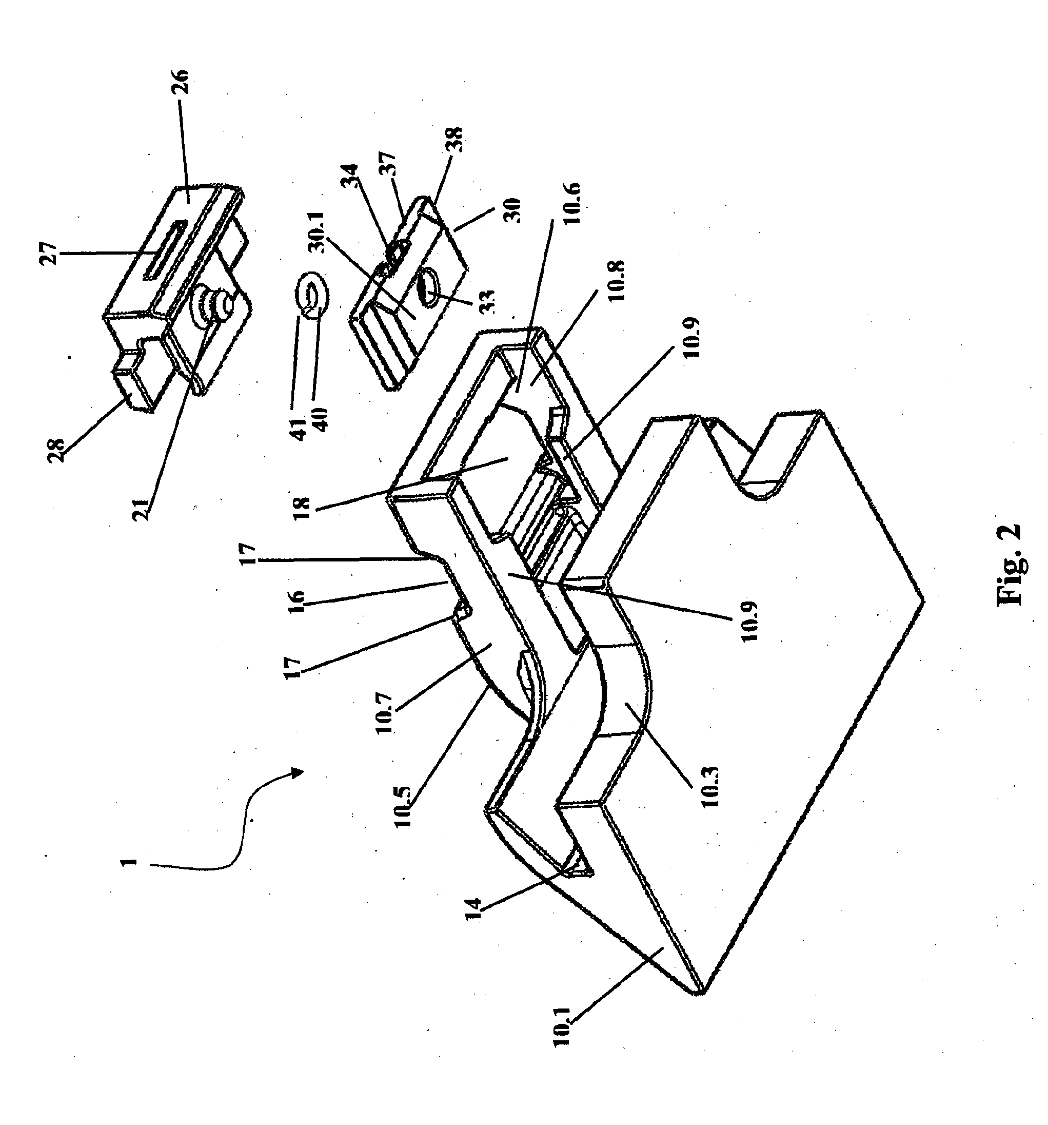
[0056]Illustrated in FIGS. 1 to 9 is an assembly 1 including a wear member in the form of a shroud 10 which receives a leading edge or lip of an excavation bucket, a lock 20, a base 30 and as visible in FIG. 2, a retaining spring 40. For ease of illustration the assembly 1 is not shown on the lip of a bucket, but in the cross-section of FIG. 4 a phantom outline of the cross-section of such a lip 80 is illustrated

[0057]The shroud 10, includes a forward digging tip 10.1 and a lifting hook 10.2. The rear of shroud 10 is bifurcated so as to receive lip 80. The lower arm 10.3 of the bifurcation is adapted to sit below the lip 80, and as can be seen in FIG. 3 preferably including a scallop formation 10.4 to decrease weight and the amount of metal in the shroud 10, and yet maintain the structural integrity of lower arm 10.3.

[0058]The upper arm 10.5 of the bifurcation includes aperture 18 which communicates from the upper wear surface of the shroud 10 to the base receiving formation 10.6 on...


PUM


Abstract

The present invention provides a wear assembly (1) including a wear member (10, 100, 110) to be mounted to an implement or apparatus to be protected, a base member (30, 300, 330) to be attached to the implement or apparatus, a lock member (20, 21) to lock said wear member (10, 100, 110) to said base member (30, 300, 330), said wear member (10, 100, 110) including or receiving said lock member (20, 21) and said base (30, 300, 330) including at least one aperture (33) in which is located a releasable retaining means (40) to releasably hold a portion (22) of said lock member (20, 21). The wear member can be: shroud; a tile shroud; a tooth; a replaceable tip. The base member can be: a base for a shroud, a base for a tile shroud; an adaptor for a tooth; an adaptor for a replaceable tip. The implement or apparatus can be: an excavation bucket; a grader blade; a chute; an excavation bucket edge; an excavation bucket surface; dump or haul truck load carrier; an ore or mineral handling apparatus.

Description

FIELD OF THE INVENTION [0001]The present invention relates to wear assemblies, locks and bases utilised in attaching wear members, such as shrouds or tile shrouds, to implements, such as buckets and excavation tools, chutes, mills or tips or teeth to adaptors mounted on such implements.BACKGROUND OF THE INVENTION[0002]There exist many different systems for the interlocking of components of a wear assembly. The disassembly of such wear assemblies tends to be a tedious and difficult task and users are seeking better and more efficient disassembly processes which do not involve a hammer to effect the disassembly by the knocking out of components.[0003]Any reference herein to known prior art does not, unless the contrary indication appears, constitute an admission that such prior art is commonly known by those skilled in the art to which the invention relates, at the priority date of this application.SUMMARY OF THE INVENTION[0004]The present invention provides a wear assembly including ...

Claims


Application Information

Patent Timeline
IPC IPC(8): E02F9/28
CPCE02F9/2825E02F9/2883E02F9/2841
Inventor ANISY, MARKSURREY, PAULHIBBERT, TREVOR
Owner CUTTING EDGES REPLACEMENT PARTS
Why Eureka
Try Eureka