Spinal fusion system and method for fusing spinal bones

a spinal cord and fusion system technology, applied in the field of spinal fusion system and spinal bone fusion, can solve the problems of inability to retropulsion the inter-body device and graft material into the spinal cord, inability to easily insert graft material from an anterior direction, and inability to retrofit the grafting material, etc., to facilitate the insertion of graft material, facilitate the fixing of a relative relation, and facilitate the effect of providing a cover

Active Publication Date: 2005-03-31
X SPINE SYST
View PDF72 Cites 91 Cited by
  • Summary
  • Abstract
  • Description
  • Claims
  • Application Information

AI Technical Summary

Benefits of technology

[0009] It is, therefore, one object of the invention to provide a spinal fusion system and method which utilizes a housing that can be inserted, but comprises features which, for example, enables the device to float relative to a cover, facilitates retaining any graft material within the device, facilitates fixing a relative relation among or between spinal bones, facilitates providing a cover for covering one or multiple devices, and / or includes locking features that facilitates preventing the screws which secure the cover to the spinal bones from the retracting.

Problems solved by technology

Among some of the problems associated with the prior art devices is that after the device is inserted into a patient during a surgical procedure, there was a possibility of retropulsion of the inter-body device and graft material into the spinal cord or other neurological element.
Another problem with the prior art devices is that grafting material, which was inserted into the devices during the surgical procedure, could not easily be inserted from an anterior direction.
Moreover, in some of the prior art devices, the cover, if any, was typically fastened directly to the device and to spinal bones, which prevented the cover from being capable of moving relative to the device.
In addition, in devices that used a cover, the cover did not function to both retain the grafting material in the device and simultaneously fix the spinal bones relative to each other.

Method used


Image

  • Spinal fusion system and method for fusing spinal bones
  • Spinal fusion system and method for fusing spinal bones
  • Spinal fusion system and method for fusing spinal bones

Examples


Embodiment Construction

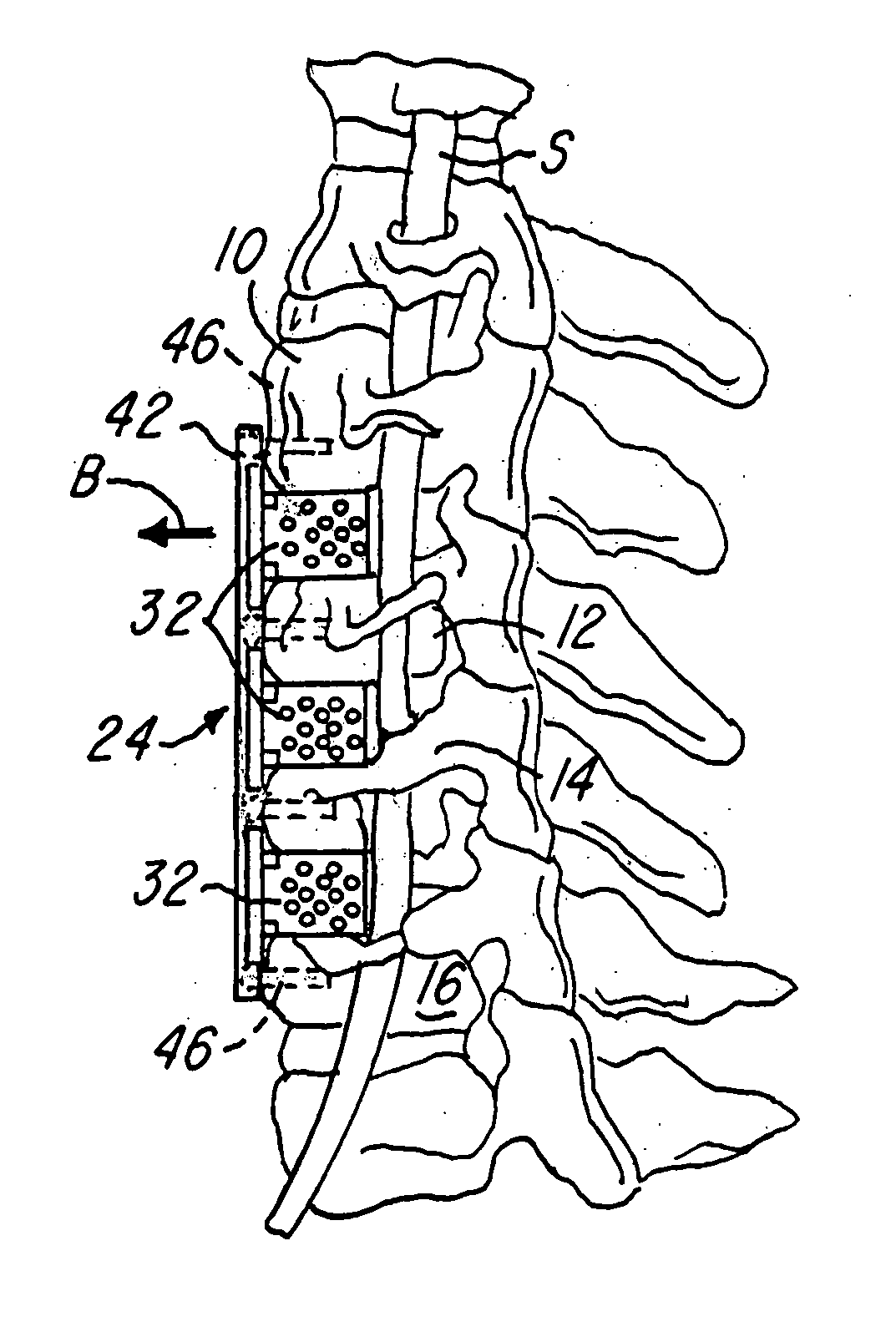
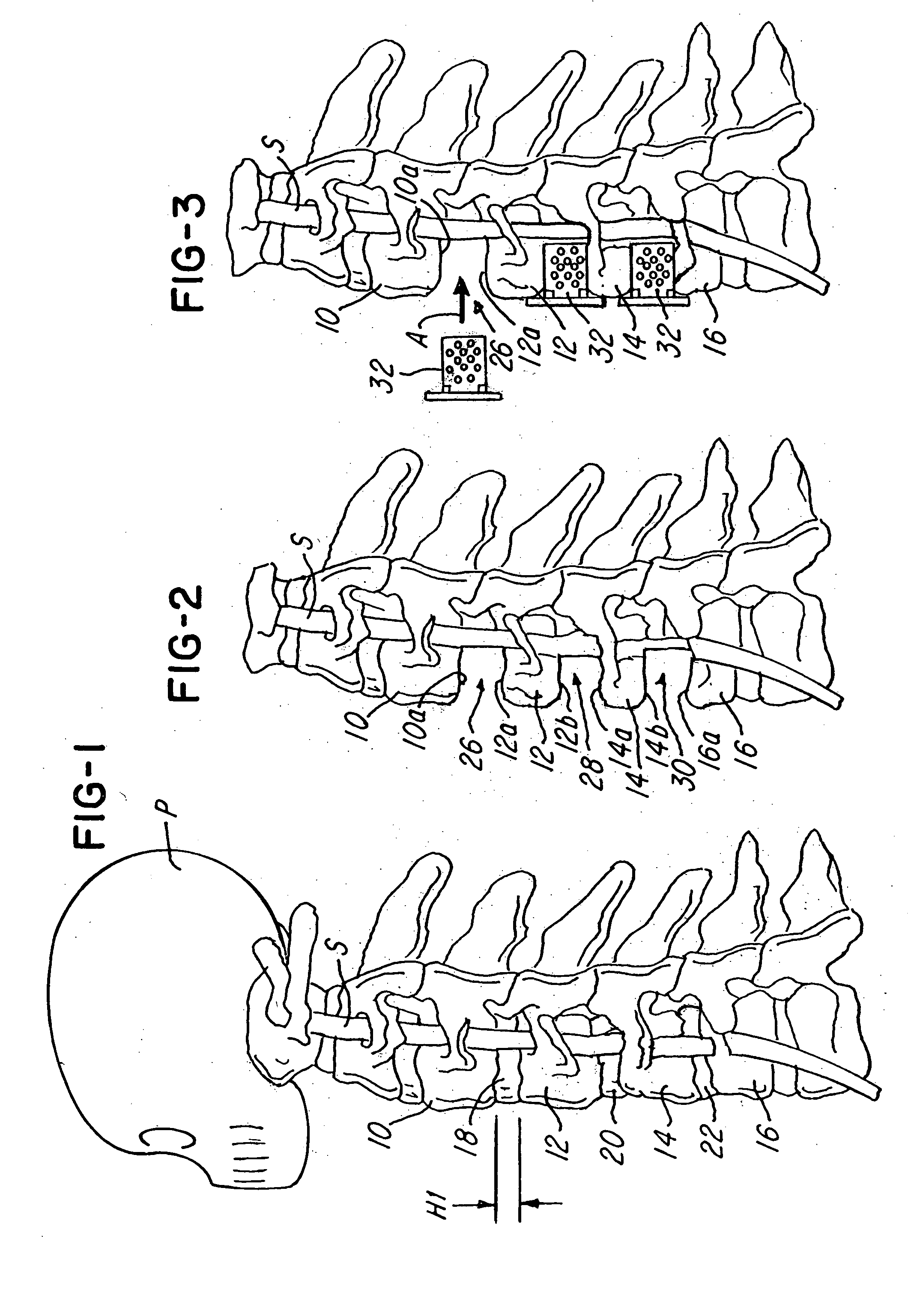
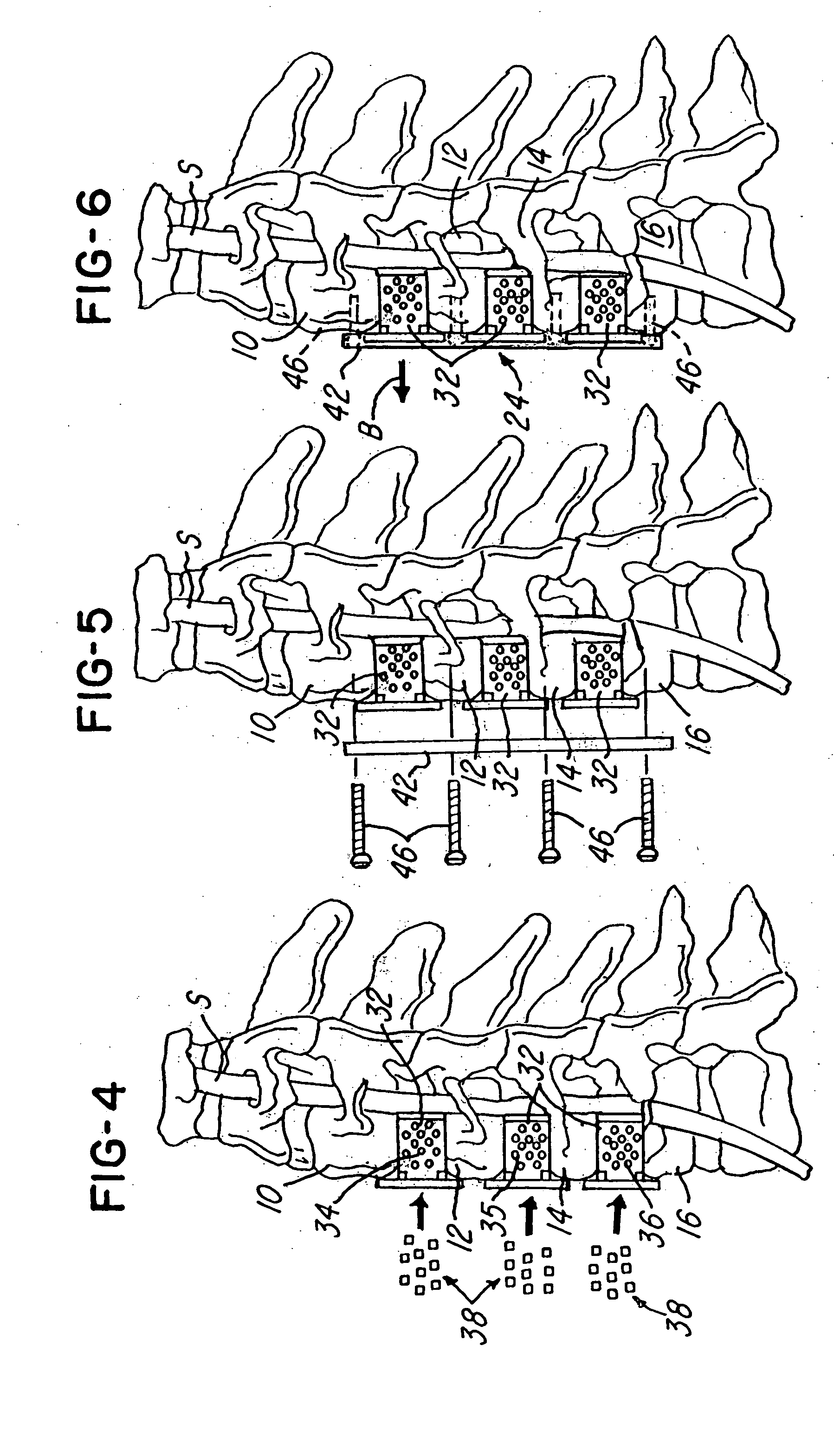
[0048] Referring now to FIG. 1, a partial side view of a patient or person P is shown having a spinal column S and a plurality of spinal bones, such as vertebrae, 10, 12, 14 and 16. Note that a disc, such as discs 18, 20 and 22 in FIG. 1, is located between adjacent pairs of spinal bones (e.g., between bones 10 and 12, 12 and 14, and 14 and 16). During a spinal fusion procedure, such as a discectomy, the discs 18, 20 and 22 may be removed so that adjacent vertebrae may be fused together

[0049]FIG. 2 illustrates a fragmentary view of the spinal column S shown in FIG. 1, with the discs 18, 20 and 22 removed. It should also be understood that during another surgical procedure, such as a vertebrectomy, it may be desired to remove part of all of one of the spinal bones 10-16, as illustrated in FIG. 13. In this type of neurological procedure, it may also be desired to fuse adjacent spinal bones together for reasons that are conventionally known. This invention provides means for facilitat...


PUM


Abstract

This invention relates to a spinal fusion system and method for use as a prosthetic implant. The system and method includes a housing dimensioned to be situated between adjacent spinal bones, such as adjacent vertebrae. The housing cooperates with the spinal bones to define a graft area for receiving graft material, which may be inserted anteriorly into the housing during a surgical operation such as a vertebrectomy or discectomy. A housing may have various features such as migration preventers to prevent the housing from migrating posteriorly towards a spinal column during or after insertion of the housing; a plurality of projections or crossbars may be removably inserted into the housing and can be used with a cover that permits the housing to “float” relative thereto.

Description

BACKGROUND OF THE INVENTION [0001] 1. Field of the Invention [0002] This invention relates to a veritable prosthetic system and device and a method for implanting the device and, more particularly, to a spinal fusion system and method for fusing spinal bones. [0003] 2. Description of the Related Art [0004] Many types of prosthetic devices have been proposed in the past. For example, U.S. Pat. No. 5,192,327 to Brantagan concerns a surgical prosthetic modular implant used singularly or stacked together to support and fuse together adjacent vertebrae or to totally or partially replace one or more vertebrae in a vertebral column. Other surgical implant devices and methods are shown in U.S. Pat. Nos. 5,192,327; 5,261,911; 5,713,899; 5,776,196; 6,136,002; 6,159,245; 6,224,602; 6,258,089; 6,261,586; 6,264,655; 6,306,136; 6,328,738 and 6,592,586. Some or all of these devices have improved the success rate and have simplified the surgical techniques in inter-body veritable fusion. [0005] Amo...

Claims


Application Information

Patent Timeline
Patent Type & Authority Applications(United States)
IPC IPC(8): A61B17/70A61B17/80A61F2/00A61F2/28A61F2/30A61F2/44
CPCA61B17/7059A61F2220/0041A61B17/8052A61F2/30744A61F2/44A61F2/447A61F2002/2835A61F2002/30439A61F2002/30507A61F2002/30517A61F2002/30578A61F2002/30616A61F2002/30785A61F2002/30794A61F2002/4475A61F2002/449A61F2220/0025A61B17/8042A61F2002/30433A61F2002/30593A61F2002/3079
Inventor KIRSCHMAN, DAVID LOUIS
Owner X SPINE SYST
Why Eureka
Try Eureka