Puncture aid with protection against reuse

a puncture aid and reuse technology, applied in the field of disposable puncture aids, can solve the problems of user contamination or infected by blood residue, unpreventable and inability to use a tool again to tension the puncture aid, so as to prevent reuse of puncture aids

Inactive Publication Date: 2007-08-09
ROCHE DIABETES CARE INC
View PDF7 Cites 81 Cited by
  • Summary
  • Abstract
  • Description
  • Claims
  • Application Information

AI Technical Summary

Benefits of technology

[0009] The present invention provides a system to prevent reuse of a puncture aid. According to exemplary embodiments, the puncture aid comprises a housing which has an opening and in which a lancet holder with a lancet is displaceably mounted, the lancet holder being connected to a spring element, and the lancet holder having at least one bearing element, and in which housing at least one support surface is arranged in such a way that the bearing element rests on the support surface in a first position of the lancet holder. A trigger unit is provided by means of which the lancet holder, through actuation of a trigger button, is transferred to a second position by means of a relative rotation or movement of the bearing element and the support surface with respect to one another, so that

Problems solved by technology

Allowing multiple use of a puncture aid introduces a risk of the user being contaminated or infected by blood residue present on the lancet of the puncture aid.
This puncture aid according to EP 1 371 329 A1 has the disadvantage that, by using a suitable tool in the form of an elongate element that can be inserted through the opening i

Method used


Image

  • Puncture aid with protection against reuse
  • Puncture aid with protection against reuse
  • Puncture aid with protection against reuse

Examples


first embodiment

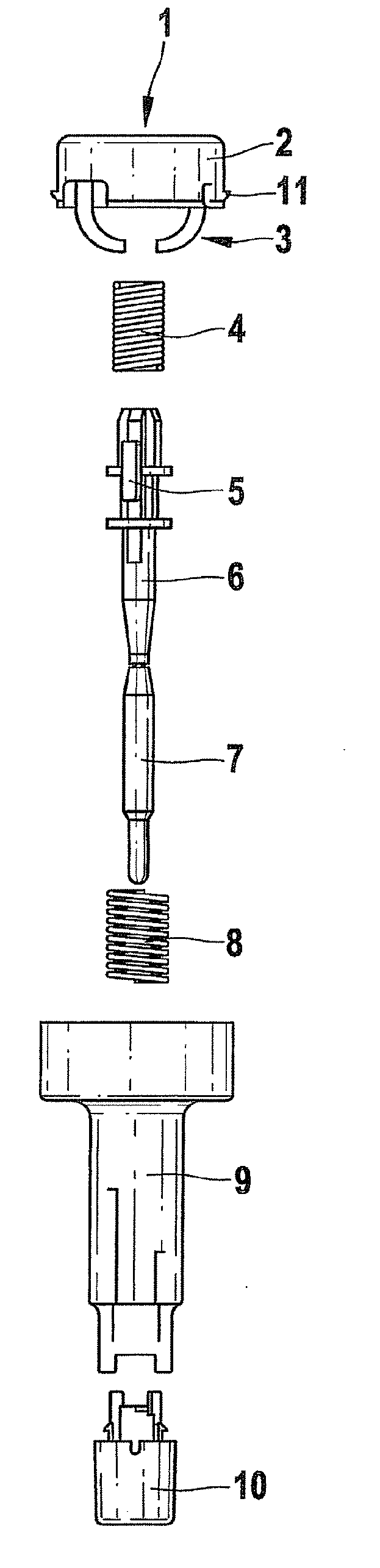
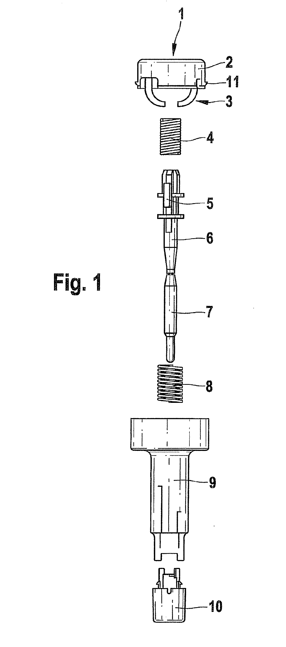
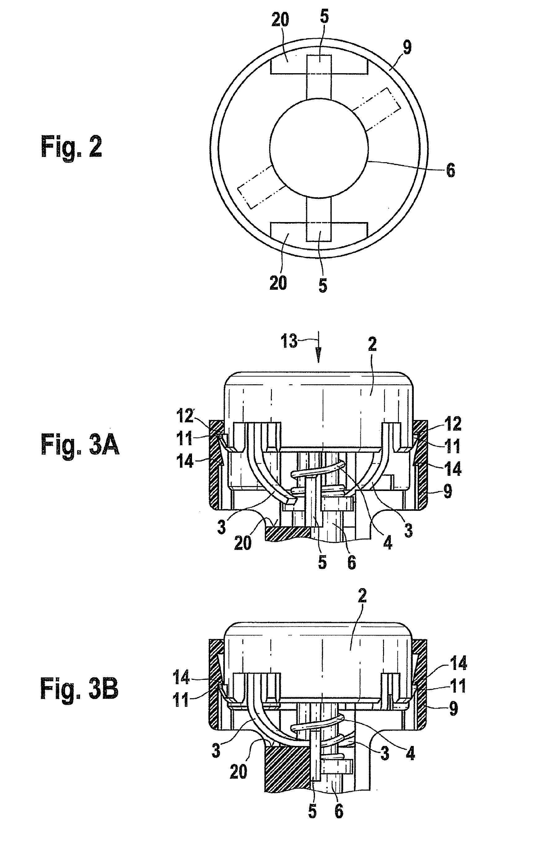
[0044]FIG. 3A shows a sectional detail of a puncture aid before the first use. The trigger is shown with its two hooks 11. Before use of the puncture aid, the hooks 11 are hooked behind two upper projections 12 of the housing 9, so that the trigger is locked in the housing 9 above lower projections 14 of the housing 9. Small hooks 3 acting as rotary drive elements are connected to the trigger button 2. In the illustrated position of the trigger button 2 (not pressed down), the small hooks 3 are spaced apart from the bearing elements 5 of the lancet holder 6, which in the first position rest on the support surfaces 20 (not shown). The drive spring 4 is in a tensioned (compressed) state. When the trigger button 2 is pressed in the axial direction 13, the trigger button 2 executes a linear movement in the axial direction. In this way, the rotary drive elements 3 are pressed against the bearing elements 5, which consequently execute a rotation movement relative to the support surfaces 2...

second embodiment

[0047]FIG. 4A shows a puncture aid before its use. The trigger button 2 of this puncture aid has two hooks 11 which hook the trigger button 2 in each case in a recess 15 of the housing 9, so that the trigger button 2 cannot be detached from the housing 9. In the puncture aid shown in FIG. 4A, the bearing elements 5 of the lancet holder 6 rest on the support surfaces 20 (not shown), and the rotary drive elements 3 (small hooks) are spaced apart from the bearing elements 5.

[0048] When the trigger button 2 is pressed down in order to trigger a puncturing process, the bearing elements 5 are displaced from the support surfaces 20 by the rotary drive elements 3 and fall into the guide grooves 25. The hooks 11 each slide through a housing opening 16 until they emerge from the housing 9 and hook in behind an edge 17 on the outside of the housing 9. This hooked position is shown in FIG. 4B. The rotary drive elements 3 are positioned on the support surfaces 20 (not shown), so that they serve ...

third embodiment

[0049]FIG. 5A shows an unused puncture aid. The trigger button 2 of this puncture aid has four hooks, namely two lower hooks 18 and two upper hooks 19. In the position shown in FIG. 5A, the lower hooks 18 are hooked in behind projections 21 on the upper edge of the housing 9, so that the trigger button 2 is held securely on the housing. The rotary drive elements 3 designed as small hooks are arranged spaced apart from the bearing elements 5 that rest on the support surfaces 20 (not shown).

[0050] By pressing the trigger button 2 down, the latter is displaced linearly in the axial direction 13. The rotary drive elements 3 are pressed against the bearing elements 5, so that the lancet holder 6 executes a rotation movement and the bearing elements 5 fall from the support surfaces 20 (not shown) into the guide grooves 25. The lancet then executes a puncturing movement. As is shown in FIG. 5B, the trigger button 2 is hooked with the upper hook 19 behind the projections 21 after the linear...


PUM


Abstract

The present invention provides a puncture aid comprising a housing in which a lancet holder with a lancet is displaceably mounted, the lancet holder being connected to a spring element. The lancet holder has at least one bearing element and the housing has a support surface arranged such that the bearing element rests on the support surface in a first position of the lancet holder. A trigger unit is provided, actuation of which transfer the lancet holder to a second position by means of a relative rotational movement of the bearing element and the support surface, so that the bearing element falls from the support surface in the second position of the lancet holder, and the tensioned spring element at least partially relaxes and moves the lancet holder such that the tip of the lancet emerges from the opening of the housing. The puncture aid includes a blocking element which is arranged such that it blocks a relative rotational movement of the bearing element and the support surface with respect to one another after the trigger unit has transferred the lancet holder to the second position with the result that reuse of the puncture aid is prevented.

Description

RELATED APPLICATIONS [0001] This application claims priority to EP 06100216.8, filed Jan. 10, 2006. BACKGROUND [0002] The present invention relates to a disposable puncture aid, and in particular, a disposable puncture aid whose reuse is prevented by a blocking element. [0003] Samples of body fluids, in particular, blood, are taken with the aim of carrying out a subsequent analysis, in order to permit diagnosis of diseases or to monitor the metabolic status of a patient. Such samples are taken by diabetics, in particular, for determining blood sugar concentration. In order to collect only small quantities of blood for diagnostic purposes, sterile, sharp lancets are normally used which, for example, are briefly inserted by hospital staff or by the patients themselves into the finger pad or into other parts of the body. In the area of home monitoring in particular, where persons without specialized medical training carry out simple analyses of blood themselves, lancets and associated ...

Claims


Application Information

Patent Timeline
IPC IPC(8): A61B17/32
CPCA61B5/15142A61B5/1411A61B5/150022A61B5/150183A61B5/150412A61B5/150519A61B5/150564A61B5/150618A61B5/150717A61B5/150916A61B5/15113A61B5/15117A61B5/15144
Inventor SCHOSNIG, STEFANHANDEL, WOLFGANGJOST, WOLFGANGKOLONKO, LYDIALIST, HANSGRIFFIS, JACKLEUTZ, BRIANSTOUT, JEFFKENNEDY, GWENNKOEPPEL, BRADLEYNOBLE, JEFF
Owner ROCHE DIABETES CARE INC
Why Eureka
Try Eureka