Automatic-locking safety needle covers and methods of use and manufacture

a technology of automatic locking and needle cover, which is applied in the direction of manufacturing tools, infusion needles, other medical devices, etc., can solve the problems of reducing the likelihood of transferring blood or tissue-born diseases from one patient, and the risk of accidental needle sticks

Active Publication Date: 2012-04-24
STA MED
View PDF175 Cites 53 Cited by
  • Summary
  • Abstract
  • Description
  • Claims
  • Application Information

AI Technical Summary

Benefits of technology

[0007]In certain arrangements, a method of protecting against unintentional needle sticks with a needle cover can comprise: forming a housing, wherein the housing at least partially contains the needle is and configured to couple to a syringe, wherein the housing includes an axis and a guide member; forming a sleeve, wherein the sleeve includes a plurality of tracks configured to receive the guide member, wherein the sleeve is configured to receive a distal tip of the needle and to move between a first position and a second position, wherein the first position covers the distal tip of the needle and the second position exposes the distal tip of the needle, and wherein the sleeve rotates with respect to the housing during at least some of the movement; and wherein movement of the sleeve engages a first locking member configured to inhibit further movement of the sleeve. In some embodiments, the first locking member inhibits reuse of the needle cover by inhibiting rotation of the sleeve. In some embodiments the first locking member inhibits reuse of the needle cover by axial movement of the sleeve. The movement of the sleeve can further engage a second locking member configured to inhibit reuse of the needle cover. In some embodiments, the second locking member inhibits reuse of the needle cover by inhibiting axial movement of the sleeve. In some embodiments, the second locking member inhibits reuse of the needle cover by inhibiting rotation of the sleeve.

Problems solved by technology

Among other concerns, this removal and replacement procedure creates a risk of accidental needle sticks.
This procedure reduces the likelihood of transferring blood or tissue-born diseases from one patient to another.

Method used


Image

  • Automatic-locking safety needle covers and methods of use and manufacture
  • Automatic-locking safety needle covers and methods of use and manufacture
  • Automatic-locking safety needle covers and methods of use and manufacture

Examples


Embodiment Construction

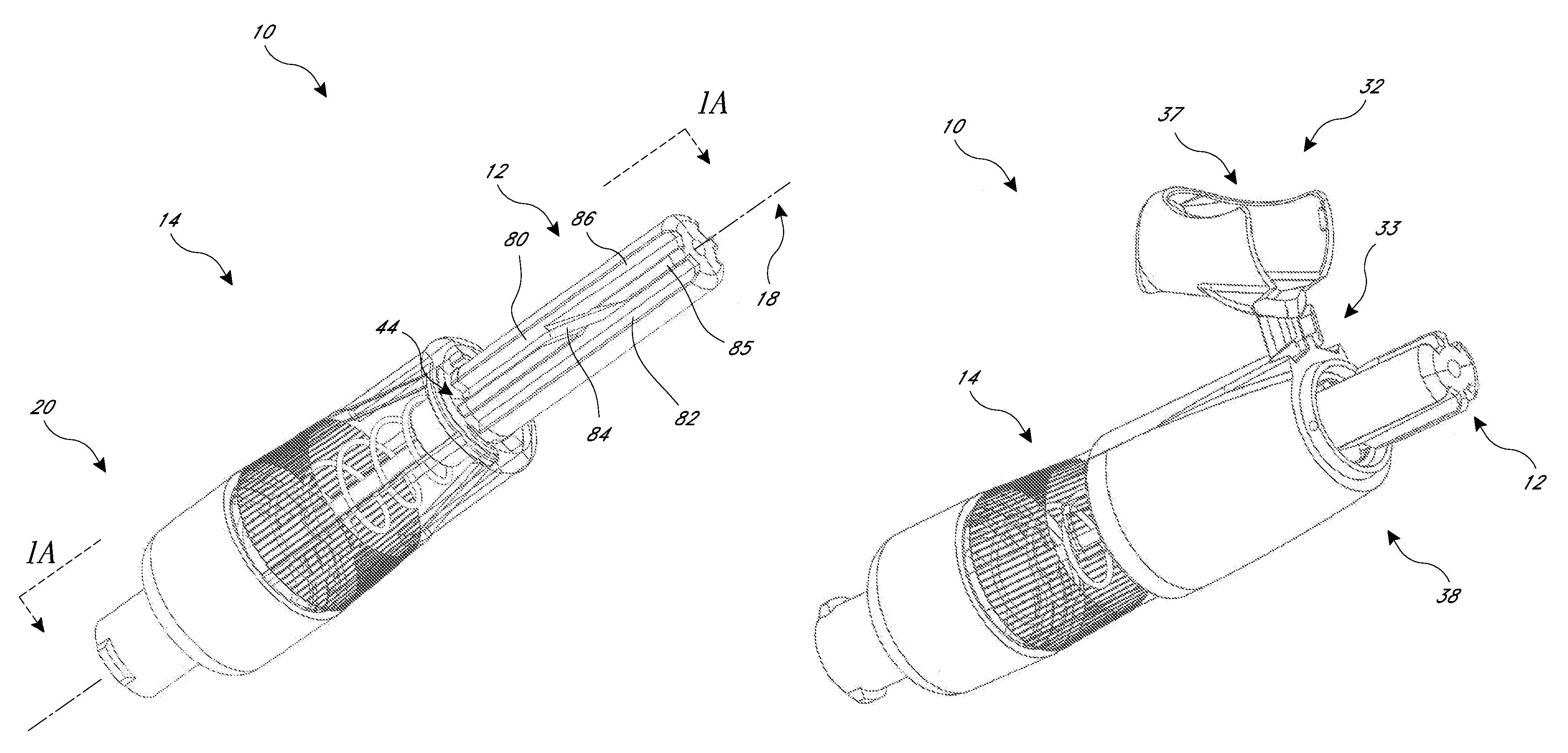
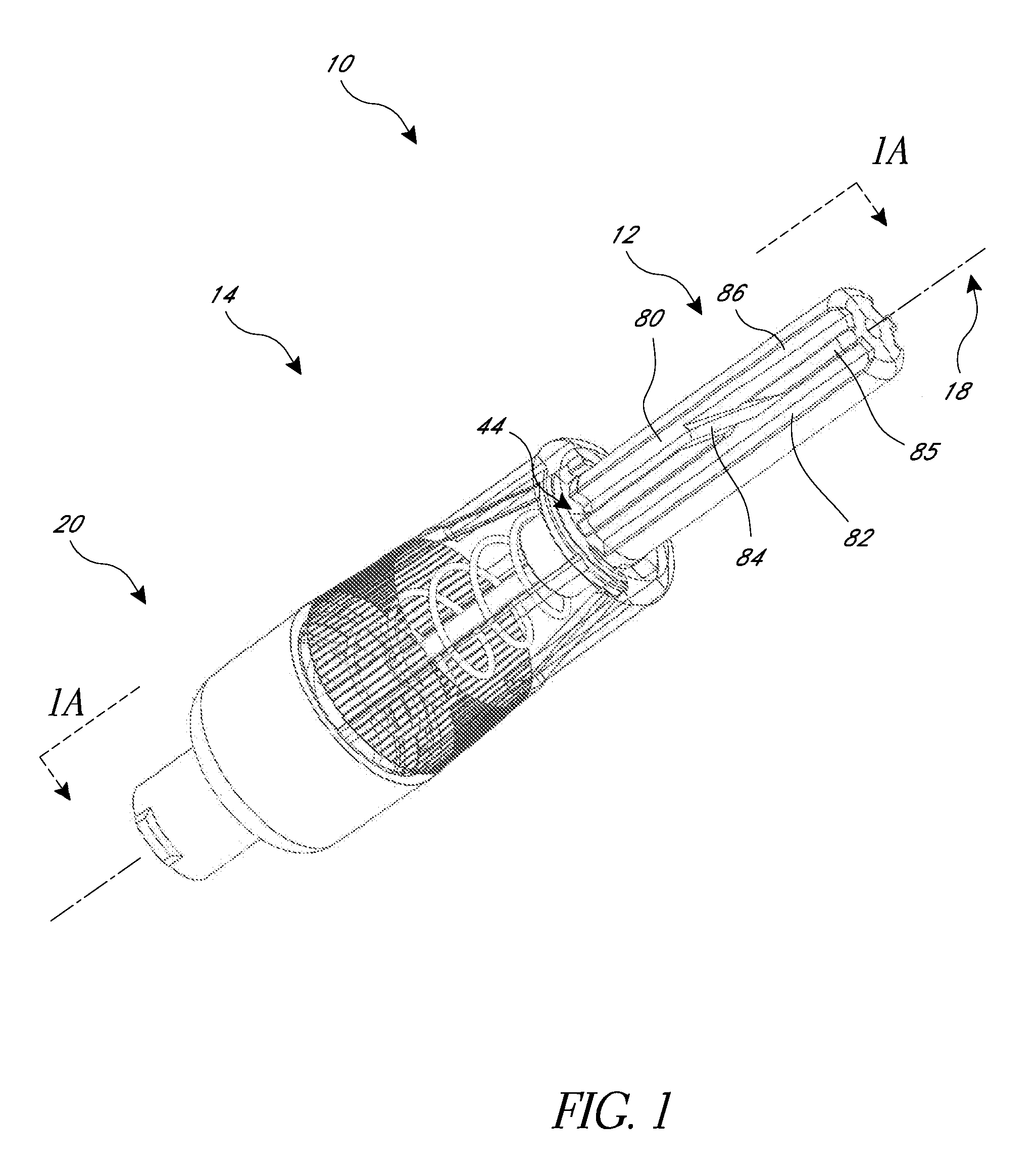
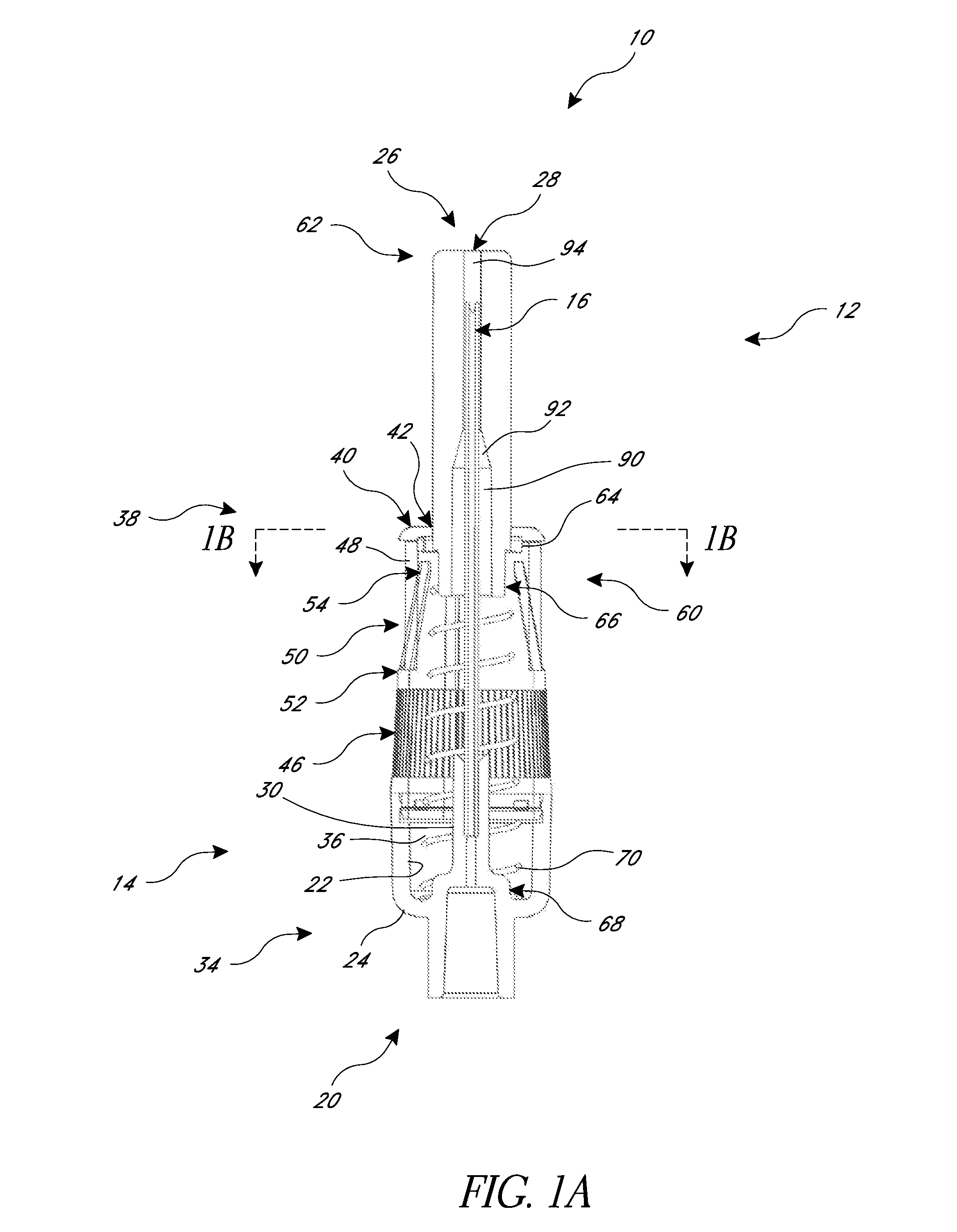
[0047]A variety of examples of needle covers are described below to illustrate various examples that may be employed to achieve the desired improvements. These examples are only illustrative and not intended in any way to restrict the general inventions presented and the various aspects and features of these inventions. For example, although embodiments and examples are provided herein in the medical field, the inventions are not confined exclusively to the medical field and certain embodiments can be used in other fields. Furthermore, the phraseology and terminology used herein is for the purpose of description and should not be regarded as limiting. No features, structure, or step disclosed herein is essential or indispensible.

[0048]FIG. 1 illustrates a needle cover 10 that may be removably coupled to a standard or specially configured syringe (not shown). The cover 10 includes features and components, discussed below in detail, that generally obscure, protect, or hide at least a ...


PUM

PropertyMeasurementUnit
lengthaaaaaaaaaa
axial lengthaaaaaaaaaa

Abstract

A single-use needle cover configured to obscure, protect, or hide at least a portion of a needle from view before, during, and / or after an injection and / or aspiration procedure is disclosed. In some embodiments, the cover includes a housing at least partially containing the needle and configured to couple to a syringe, wherein the housing includes an axis and a guide member. In some embodiments, a sleeve has a plurality of tracks configured to slidingly receive the guide member, wherein the sleeve is configured to retract, extend, and rotate with respect to the housing. In some embodiments, after the sleeve has been retracted and extended one time, a first locking member inhibits further retraction of the sleeve and a second locking member inhibits rotation of the sleeve.

Description

BACKGROUND[0001]Certain embodiments disclosed herein relate to needle covers and needle cover assemblies for medical devices, such as syringes, and are particularly related to obscuring at least a portion of the needle from view and aiding in the transfer of fluids.DESCRIPTION OF THE RELATED ART[0002]Syringes are used throughout the medical industry for the injection and withdrawal of a wide variety of fluids and solutions into and from the human body. Due to the numerous potential hazards associated with the handling and manipulation of bodily fluids, and particularly blood, there are a number of known safety features that are frequently incorporated into various types of syringes and syringe needles. For example, many syringe needles are provided with a removable cap that generally prevents needle sticks while the cover is in place. When the cap is removed, the needle is exposed. These caps are removed before an injection and / or aspiration procedure and replaced after the injectio...

Claims


Application Information

Patent Timeline
Patent Type & Authority Patents(United States)
IPC IPC(8): A61M5/00
CPCA61M5/326A61M5/3272A61M5/422A61M5/3245A61M2005/3258A61M2205/59A61M2005/3267Y10T29/49863A61M2005/3247A61M2207/00Y10T29/49826
Inventor RUBINSTEIN, SERGIOROSENBERG, SAMUELMOSLER, THEODOREOUYANG, TIANHONGFOSHEE, DAVIDGODFREY, MARK W.
Owner STA MED
Why Eureka
Try Eureka