Safety syringe

a safety syringe and syringe technology, applied in the field of hypodermic syringes, can solve the problems of preventing mass production and use of safety syringes, bulky devices, and high manufacturing costs, and achieves the effects of reducing the possibility of inadvertent needle sticking, easy manufacturing, and low manufacturing cos

Inactive Publication Date: 2003-11-13
MEDEXEL KOREA
View PDF3 Cites 49 Cited by
  • Summary
  • Abstract
  • Description
  • Claims
  • Application Information

AI Technical Summary

Benefits of technology

[0015] It is an object of the present invention to provide a safety syringe that minimizes the possibility of inadvertent needle sticks;
[0016] It is an object of the present invention to provide a safety syringe that prevents reuse of the syringe after one use;
[0017] It is an object of the present invention to provide a safety syringe that is inexpensive to manufacture;
[0018] It is an object of the present invention to provide a safety syringe that is easy to make without quality problems;
[0019] It is a further object of the present invention to provide a safety syringe that is simple to use;
[0021] It is a further object to provide a safety syringe in which if the plunger and needle holder are inadvertently coupled together they may be easily separated.

Problems solved by technology

Initially such devices were bulky, expensive to manufacture and did not function well.
Over the years as the art progressed they became easier to make and operate, but still problems remain which have prevented mass manufacture and use of safety syringes.
This manipulation near the needle is believed fraught with danger.
This device is also believed unnecessarily complex.
Given the variations in wall thickness of the barrel section to provide the slots, and the complicated geometry of the needle holder cavity for the snap connection, this device is believed difficult and expensive to manufacture, and subject to quality problems.

Method used


Image

  • Safety syringe
  • Safety syringe
  • Safety syringe

Examples


first embodiment

[0087] Some important aspects of the safety syringes are as follows:

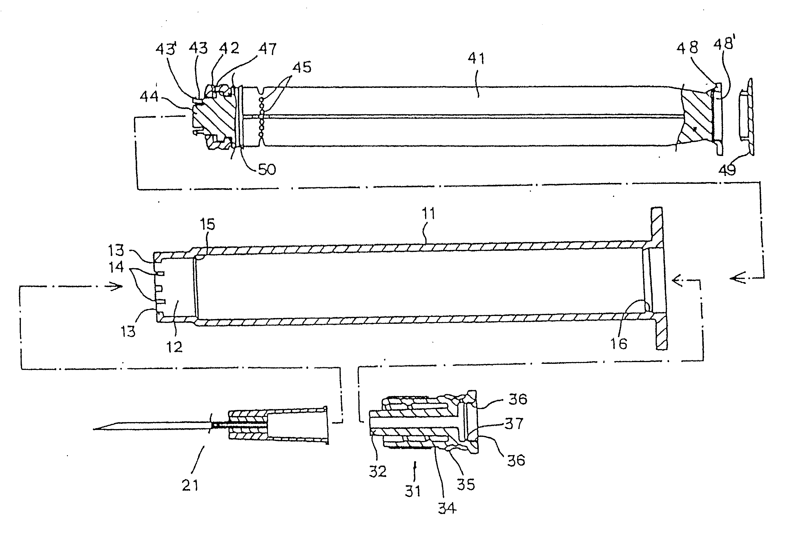
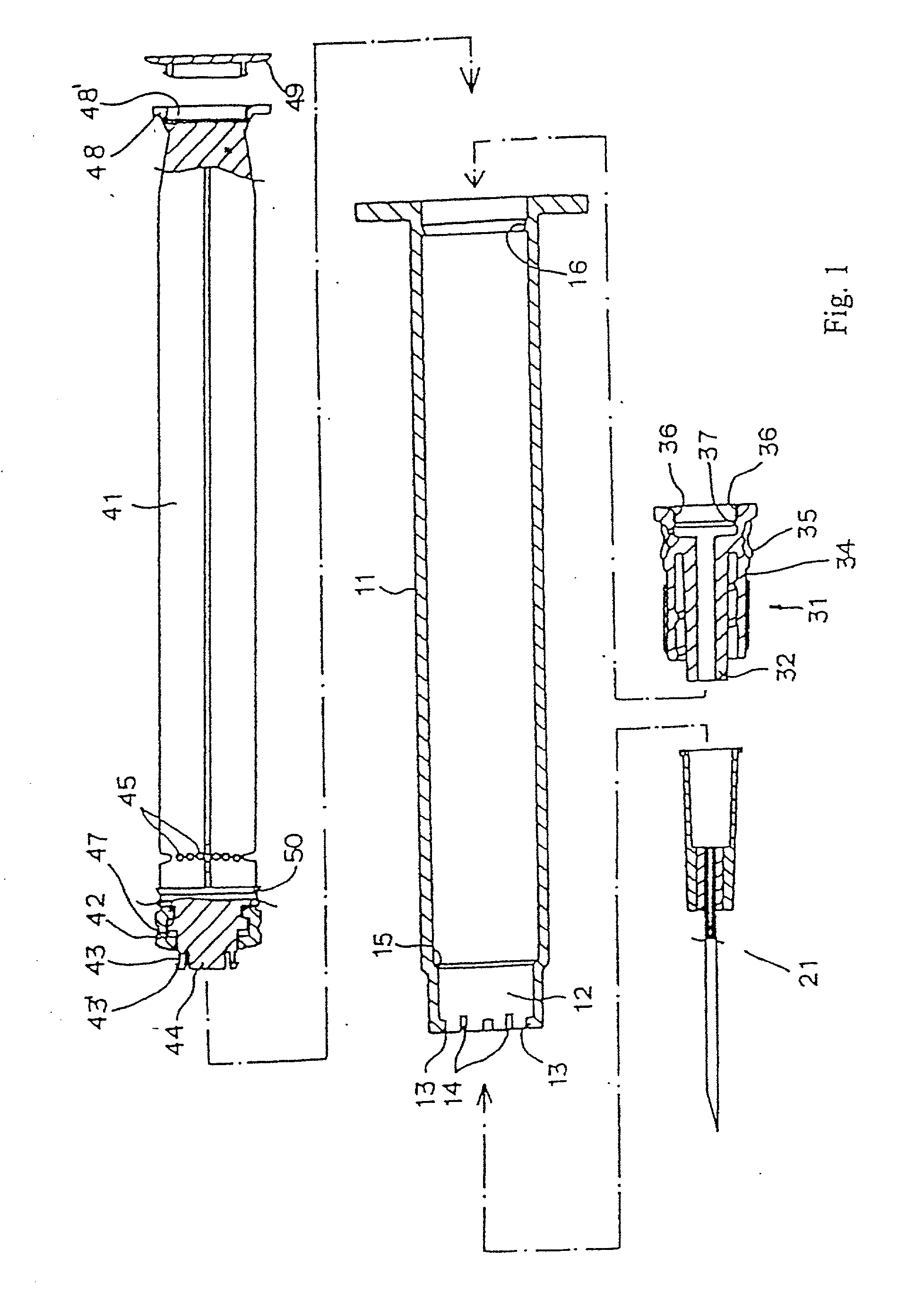
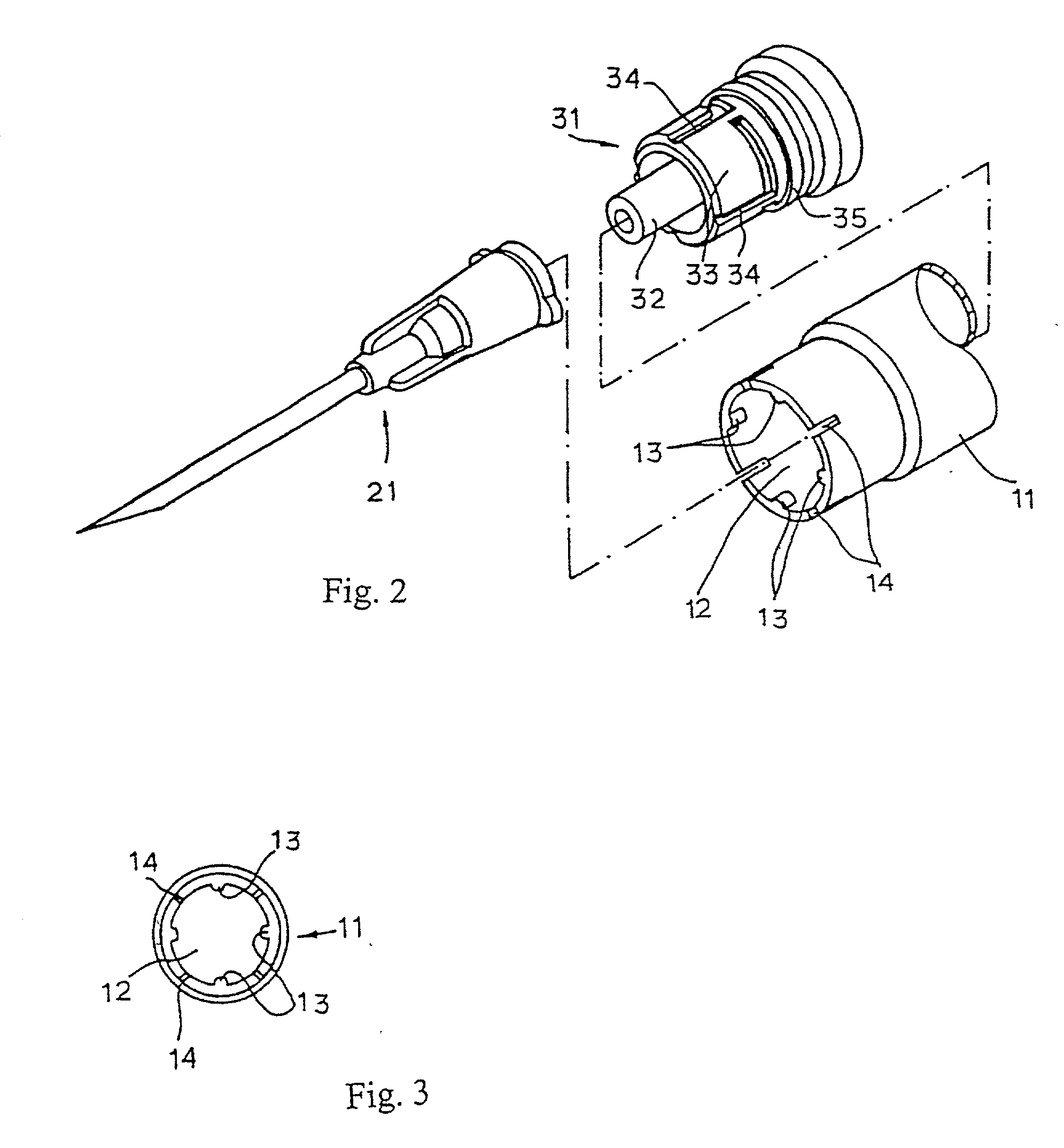
[0088] It has a cylinder to suck in injection. Piston and plunger are in the cylinder while the ordinary syringe has the syringe needle affixed to the syringe, this device has the cylinder (11), syringe needle (21), syringe needle inserter (31) and plunger respectively as parts of its structure. At the insert hole (16) of the above said cylinder (11) tip are a host of projections (13) and incised grooves (14) arranged alternatively one after another. Cylinder's (11) inner face has stopping sill and hooking sill in the rear. At the center of the syringe needle inserter is a syringe needle fixer to fix syringe needle. Outer barrel shaped outer face of the syringe needle fixer has a number of "L" shaped grooves for projections (13) formed on the inner face of the insert hole (12) to set in. Packing (35) is set in the rear. On the upper and lower part of the inner face of the rear part are projections (36). Inside the ...

second embodiment

[0119] Some important aspects of the safety syringe are as follows:

[0120] This safety single use syringe is composed of a barrel (11), a needle (21), a plunger (41) and a needle inserting device (31), same as a general syringe which has a barrel into which the liquid medicine is sucked, a piston and a plunger inside the barrel, and a needle is put on the front tip of the barrel. There s a number of projections (13) in the inside of the front end of an inserting hole (12) of the above barrel (11), the circular stop prominence (15) at the inner surface of a barrel (11), a circular restraining prominence (16) inside the rear end of a barrel, a needle fixing device (32) to insert a needle (21) at the center of a needle inserting device (31), a number of "L" shaped grooves (34) with the wide entrances at an outer surface (33) of a cylindrical part of a needle fixing device (32) in order to be assembled with a projection (13) located at an inner surface of an inserting hole (12) of the a...

third embodiment

[0126] [Third Embodiment]

[0127] Referring now to FIGS. 26-32, a third embodiment of the present invention may be described. Referring to FIG. 26, shown disassembled are portions of a safety syringe including a hollow needle 21, a thin-walled cylinder or barrel 11 (the forward end being shown), a needle holder 61 and a plunger 71. This embodiment includes an improved connection between the needle holder 61 and plunger 71. Accordingly, the aft portion of the needle holder 61 and forward portion of the plunger 71 are different from the safety syringes described above.

[0128] As best shown in FIG. 26, the aft portion of the needle holder 61 includes a generally circular opening 64 leading to a generally cylindrically cavity 66 having an inner surface 65. Around the circular opening 64 are a pair of latching members or tabs 69 which are rounded and project slightly into and aft of the circular opening 65. Inside the cylindrically cavity 66 are a pair of stops or upstanding webs 68 from th...


PUM


Abstract

The invention provides a safety syringe, which has a cylinder (11), a syringe needle (21), a needle holder (31) associated to the cylinder and adapted to hold the syringe needle, and a plunger (41) associated to the cylinder (11), wherein the plunger (41) comprises a piston (42) and serves to inject a filling of the cylinder (11) via the syringe needle (21), and wherein the plunger (41) can be coupled with the needle holder (31) arranged in the region of a front hole (12) of the cylinder (11), to retract the needle holder (31) together with syringe needle (21) into the cylinder (11) by pulling the plunger (41) once coupled to the needle holder (31) is retracted into the cylinder by rotating the plunger (41) and pulling the plunger (41) aft thereby pulling the needle holder (31) into the cylinder (11). Then the aft end of the plunger (41) is broken off, and a removable cap (49) from the aft end of the plunger (41) may be placed over the opening in the forward end of the cylinder (11).

Description

CROSS-REFERENCES TO RELATED APPLICATIONS[0001] This patent application is a continuation-in-part of application Ser. No. 10 / 048,199 filed Jan. 25, 2002, which is a continuation-in-part of application Ser. No. 09 / 550,504 filed Apr. 14, 2000.[0002] 1. Field of the Invention[0003] This invention relates generally to hypodermic syringes, and more particularly to such syringes having retractable needles after use to prevent hazardous needle sticks.[0004] 2. Description of the Related Art[0005] The idea of safety syringes with retractable needles to prevent needle sticks is well known. Initially such devices were bulky, expensive to manufacture and did not function well. Over the years as the art progressed they became easier to make and operate, but still problems remain which have prevented mass manufacture and use of safety syringes.[0006] Disposable syringes are typically made by automated, high volume plastic injection molding processes. Since these devices by design are disposable a...

Claims


Application Information

Patent Timeline
Patent Type & Authority Applications(United States)
IPC IPC(8): A61M5/31A61M5/32A61M5/50
CPCA61M5/322A61M2005/5073A61M2005/311A61M2005/3109
Inventor BANG, YOUNG CHUL
Owner MEDEXEL KOREA
Why Eureka
Try Eureka