Cervical compression plate assembly

a cervical compression plate and assembly technology, applied in the field of spinal surgery, can solve the problem of not allowing lagging of the plate to the vertebrae, and achieve the effect of avoiding a distraction pseudo-arthrosis

Inactive Publication Date: 2005-02-24
DALTON BRIAN E
View PDF14 Cites 189 Cited by
  • Summary
  • Abstract
  • Description
  • Claims
  • Application Information

AI Technical Summary

Benefits of technology

[0012] From the prior discussion, it is realized that there exists therefore a need for an improved anterior cervical plating system that is sufficiently rigid to maintain the alignment of the vertebral bodies relative to the level to be fused, capable of maintaining, as well as inducing, a compressive load across the fusion site, and capable of allowing for the motion of the vertebral bodies surrounding the level of fusion to maneuver towards each other in an effort to close any gaps between the metabolically active bone fusing as well as the bone graft that occurs due to the process of creeping substitution. This has to occur while the system is simultaneously preventing motion in all other planes. Furthermore, the system must be capable of maintaining physiologic compressive load across the fusion site independent of the patient's position while at the same time limiting any distraction which may occur in less stable systems when the patient is in the supine position, thus avoiding a distraction pseudoarthrosis.

Problems solved by technology

A drawback of the systems of the prior art is that the mechanism by which the screw fixes to the plate requires the screw to be intimately machine threaded into the plate and does not allow for lagging of the plate to the vertebrae.

Method used


Image

  • Cervical compression plate assembly
  • Cervical compression plate assembly
  • Cervical compression plate assembly

Examples


Embodiment Construction

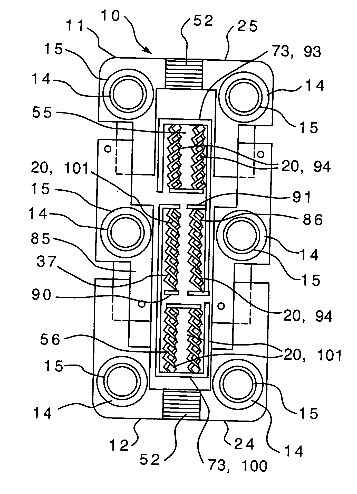
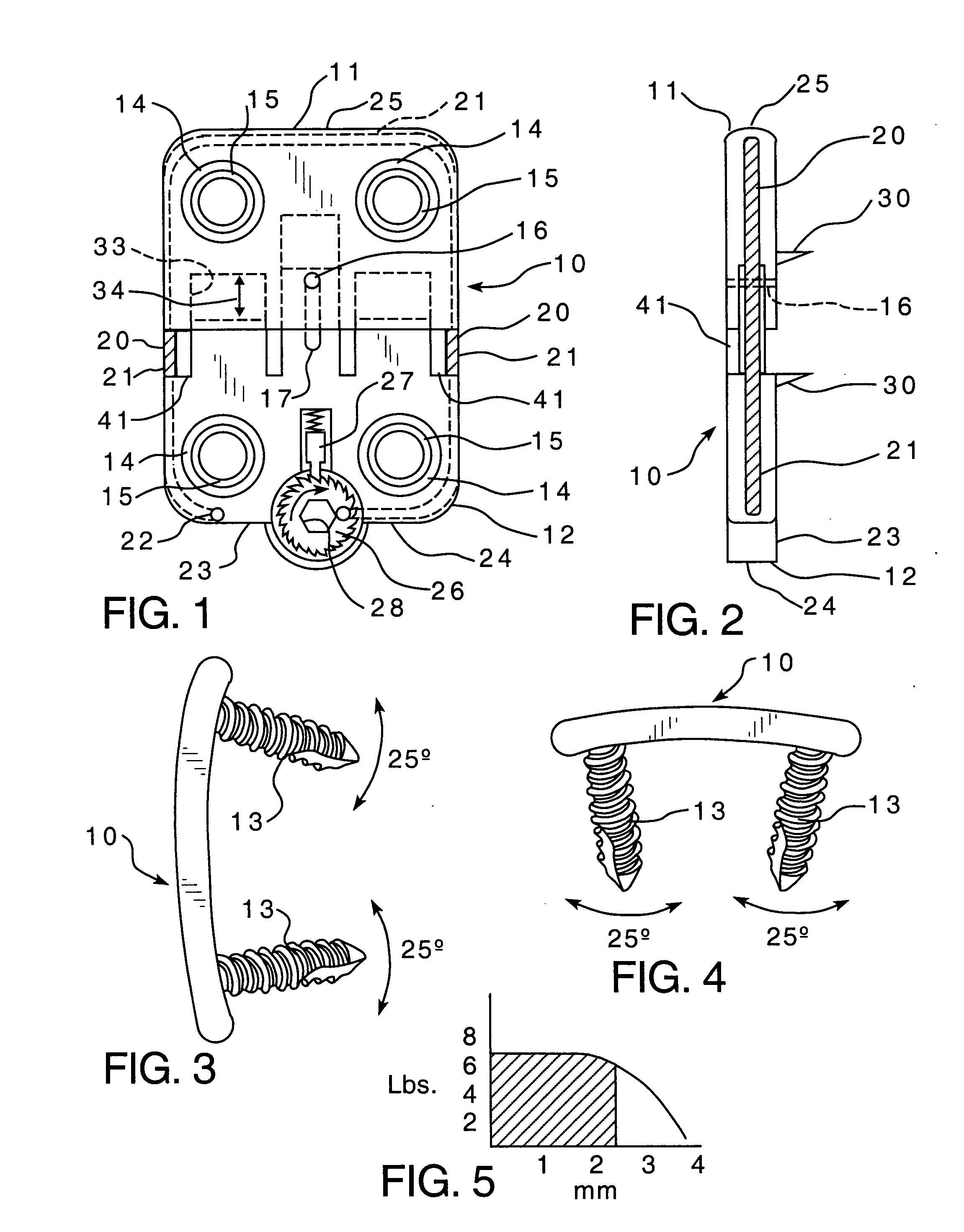
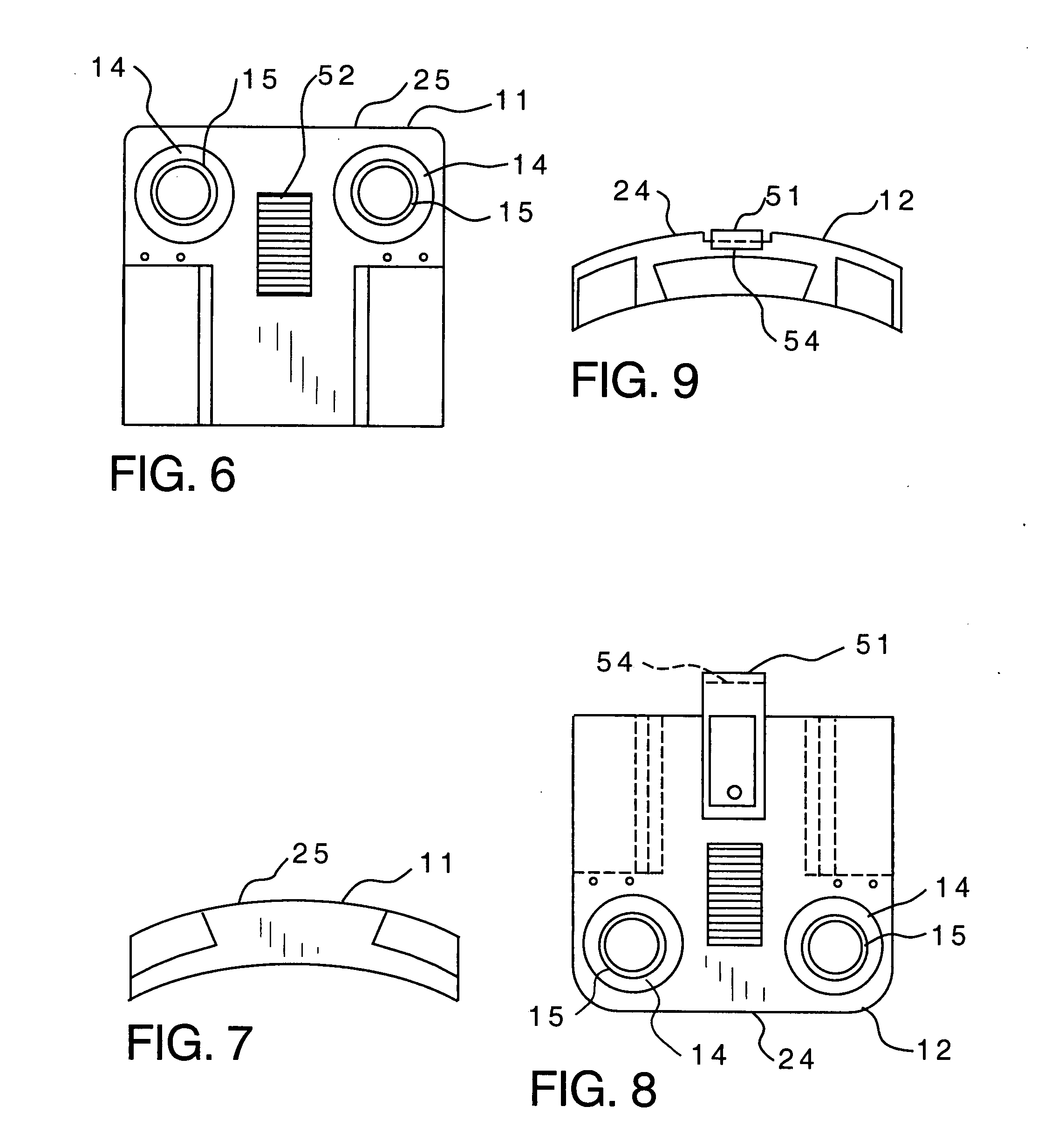
[0046] Referring first to the embodiment illustrated in FIGS. 1 and 2, the cervical compression plate assembly 10 is provided with screw receiving elements 11 and 12 at opposite ends thereof which are configured for engaging bone fixation screws 13, illustrated in FIGS. 3 and 4, extending from respective vertebral elements of the human cervical spine. The screw receiving elements 11 and 12 in this embodiment are each respectively provided with spaced identical screw head seats 14 configured for seating the heads of the bone fixation screws at different attitudes. The bone fixation screws 13 are provided with heads that have underside perimeter edges which engage the seats 14. Seats 14 are annular concave so that the screws 13 may be received within and on seats 14 at different desired attitudes or angles. This permits the surgeon to lag cervical compression plate assembly 10 securely to the cervical spine as desired. Accordingly, the angle by which the bone fixation screws 13 pass t...


PUM


Abstract

A cervical compression plate assembly having screw receiving elements at opposite ends that are configured for engaging bone fixation screws extending from respective vertebral elements. The assembly permits the distance between the screw receiving elements at opposite ends to be shortened but prevents the distance from increasing. A spring mechanism is housed within the plate assembly and is configured for continuously urging the screw receiving elements at opposite ends together for thereby providing continuous compressive loading on bone graft material disposed between the vertebral elements.

Description

BACKGROUND OF THE INVENTION [0001] This invention relates to spinal surgery, and more particularly to an anterior cervical fusion compression plate. [0002] The human spinal column is a structure consisting anteriorly of the individual vertebral bodies and the intervertebral discs. The posterior aspect of the spine consists of joints and ligaments which primarily provide a tension band for the spine. The anterior column tends to have characteristic curvatures while viewed from the sagittal plane (from the side) in the cervical, thoracic and lumbar areas, the cervical area having a lordotic or forward bow curve. These various curves are important to be maintained since they allow the spine to have sagittal balance and be agile through normal range of motion when stressed by the various contractions of muscles, etc. Disc degeneration which can lead to disc herniation as well as spur formation usually causes a lessening of the normal cervical lordosis and may lead to significant pain in...

Claims


Application Information

Patent Timeline
Patent Type & Authority Applications(United States)
IPC IPC(8): A61B17/70A61B17/80
CPCA61B17/7059A61B17/8004A61B17/8052A61B17/8047A61B17/8009Y10S606/902
Inventor DALTON, BRIAN E.
Owner DALTON BRIAN E
Why Eureka
Try Eureka