

Low phase spurious frequency synthesis method
A technology of frequency synthesis and frequency synthesizer, applied in automatic control of power, electrical components, etc., can solve the problem of spurious index, spurious index does not meet the requirements, frequency synthesizer-related and uncorrelated interference cannot be fully expected, etc. , to achieve the effect of reducing the difficulty of design, reducing the difficulty of design and debugging, and reducing the difficulty of debugging
- Summary
- Abstract
- Description
- Claims
- Application Information
AI Technical Summary
Problems solved by technology
Method used
Image

Examples
Embodiment Construction
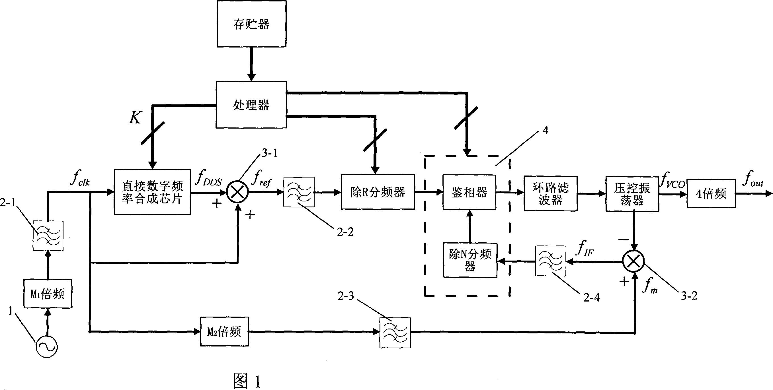
[0034] The implementation of the present invention will be described below by taking the triple modulation frequency synthesis solution as an example.
[0035] The present invention is a new triple adjustment frequency synthesis method based on multiple adjustments and flexible configuration developed on the basis of the triple adjustment frequency synthesis scheme previously completed by the inventor. The given embodiment is also based on an embodiment of the original technical solution.
[0036] The implementation example of the original technical solution is an 8mm frequency band agile frequency synthesizer developed by the inventor. Its main technical indicators are: frequency range 35GHz±200MHz, frequency step 2MHz, phase noise L (1KHz) dB ≤-87dBc / Hz, stray Φ s (f) ≤-55dBc, full-band frequency conversion time ≤15μS. In this scheme, the phase-locked loop is designed in the X frequency band, and then multiplied by 4 to the 8MM frequency band; by combining the DDS and PLL ...
PUM
 Abstract
Description
Claims
Application Information