

Clean in Place System for Beverage Dispensers
a beverage dispenser and cleaning system technology, applied in the field of beverage dispensers, can solve the problems of large slugs of undiluted concentrate, consumers can only choose from a relatively small number of products, and the separation techniques generally have not been applied to juice dispensers
- Summary
- Abstract
- Description
- Claims
- Application Information
AI Technical Summary
Problems solved by technology
Method used
Image

Examples
Embodiment Construction
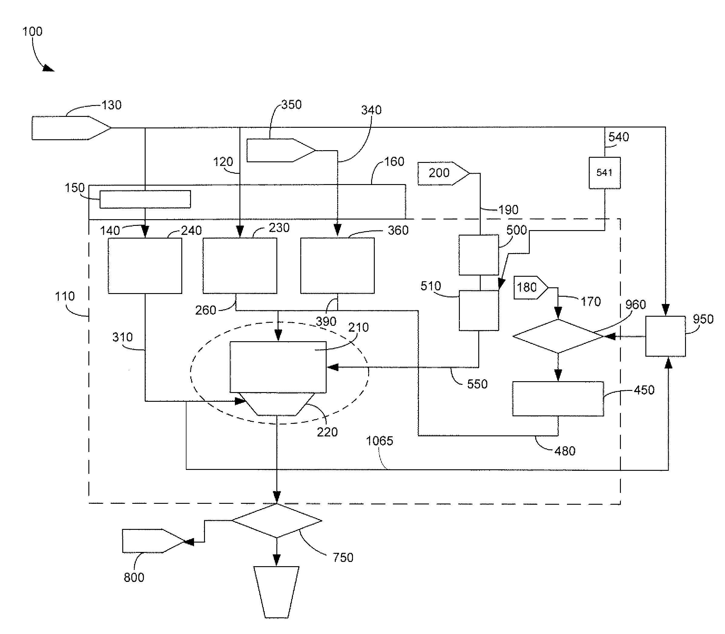
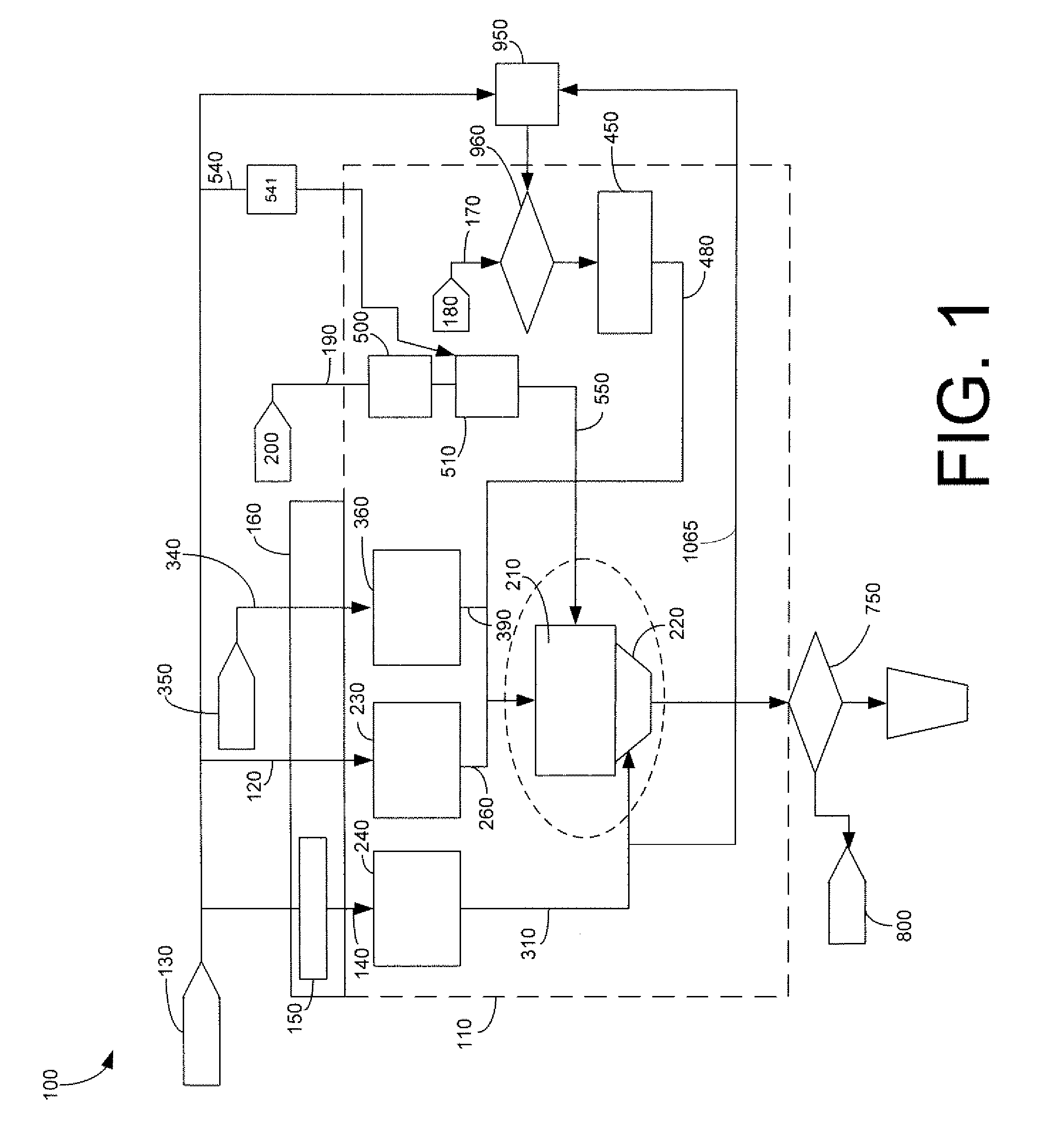
[0043]Referring now to the drawings, in which like numerals refer to like elements throughout the several views, FIG. 1 shows a schematic view of a beverage dispenser 100 as is described herein. Those portions of the beverage dispenser 100 that may be within a refrigerated compartment 110 are shown within the dashed lines while the non-refrigerated ingredients are shown outside. Other refrigeration configurations may be used herein.
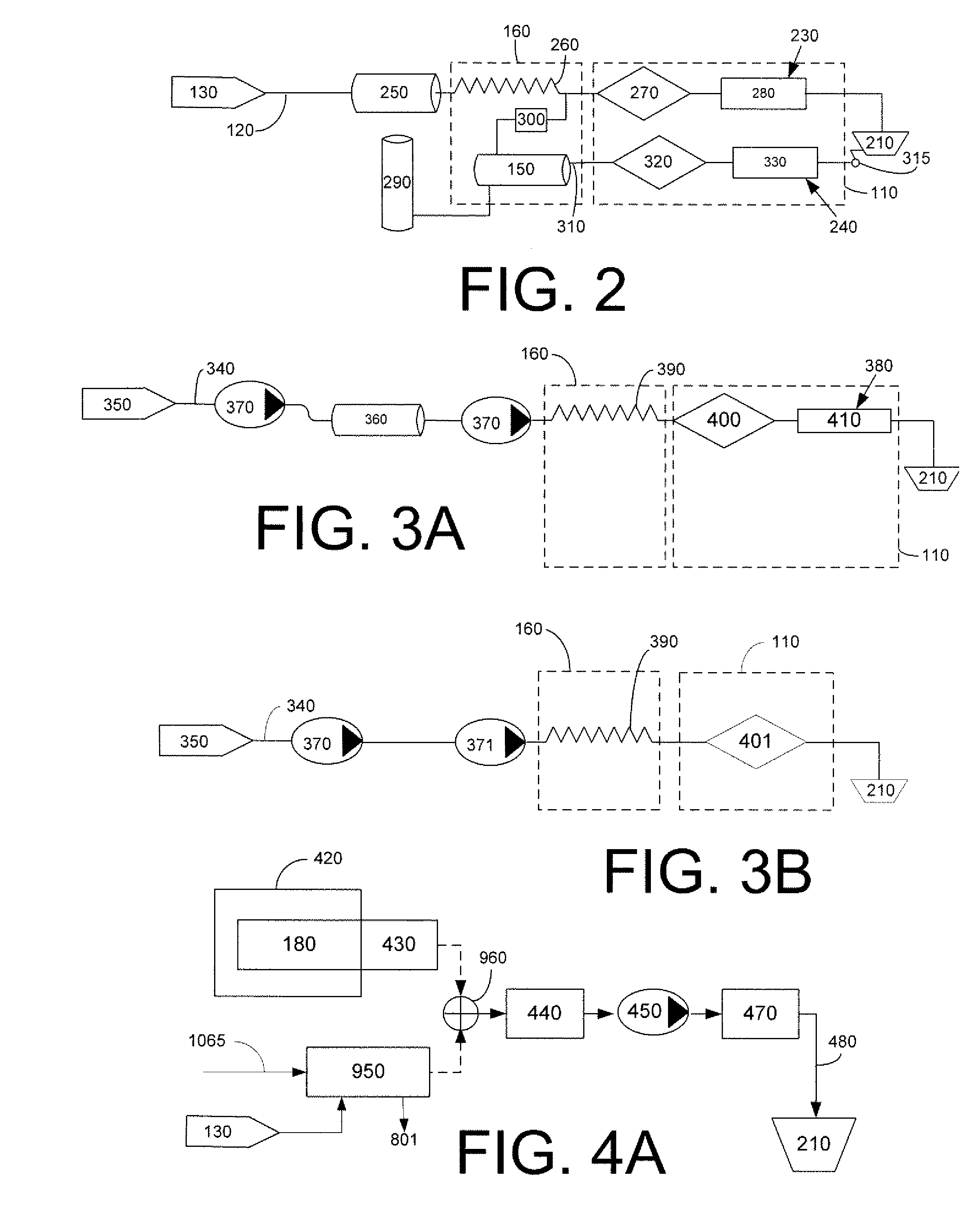
[0044]The dispenser 100 may use any number of different ingredients. By way of example, the dispenser 100 may use plain water 120 (still water or noncarbonated water) from a water source 130; carbonated water 140 from a carbonator 150 in communication with the water source 130 (the carbonator 150 and other elements may be positioned within a chiller 160); a number of macro-ingredients 170 from a number of macro-ingredient sources 180; and a number of micro-ingredients 190 from a number of micro-ingredient sources 200. Other types of ingredients may be use...
PUM
 Abstract
Description
Claims
Application Information