Valve regulation assembly

a technology for valves and assemblies, applied in the direction of machines/engines, soldering devices, applications, etc., can solve the problems of turbo lag, hp turbine no longer providing enough boost pressure to have any effect on engine performance, and low amount of exhaust gas energy

Inactive Publication Date: 2009-01-15
BORGWARNER INC
View PDF11 Cites 54 Cited by
  • Summary
  • Abstract
  • Description
  • Claims
  • Application Information

AI Technical Summary

Problems solved by technology

This lower amount of exhaust gas energy is not enough to power the larger, LP turbine, but it does provide enough energy to power the smaller, HP turbine.
During operation, as the engine begins to increase speed, the HP turbine is operated by the lower energy exhaust gases, but after the engine reaches a certain speed, the HP turbine no longer provides enough boost pressure to have any effect on engine performance.
One common problem with this type of method of turbocharging is a phenomenon called “turbo lag.” Turbo lag refers to the moment in operation where the HP turbine stops having an effect on engine performance, and the LP turbine begins to have an effect on engine performance.
At this moment in operation, there is still not enough exhaust gas energy to operate the LP turbine.
This condition is considered undesirable, and several forms of prior art have been developed to provide a smooth transition from the HP turbine to the LP turbine, thereby providing a smoother power increase to the engine.
Another common problem with two-stage turbochargers occurs at higher engine speed, when the HP turbine is not cut off from the air flow of the exhaust gas.
During this condition, sometimes called “overspeed,” the increased exhaust gas energy can cause the HP turbine to spin at speeds which may cause damage.
This is beneficial in providing boost pressure at low engine speeds, but does not aid preventing overspeed of the HP turbine.
Due to both federal and state regulations, the emissions allowed to be released during operation of motorized vehicles today are limited.
A common problem with bypass valves is that they do not provide a tight seal or barrier with the two outlet ports since the bypass valves do not articulate in response to all seal surface geometries which can change due to thermal expansion as well as build-up of oil, dirt, grim, and the like.

Method used


Image

  • Valve regulation assembly
  • Valve regulation assembly
  • Valve regulation assembly

Examples


Embodiment Construction

[0031]The following description of the preferred embodiment(s) is merely exemplary in nature and is in no way intended to limit the invention, its application, or uses.

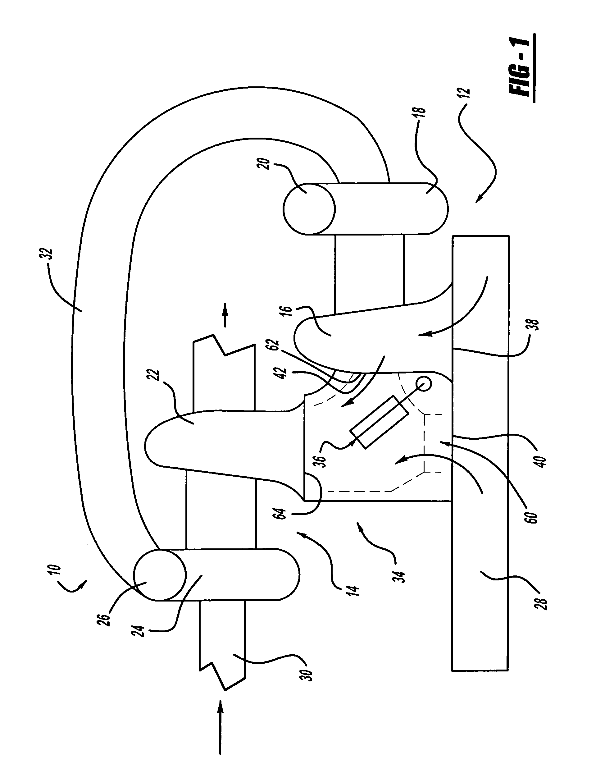
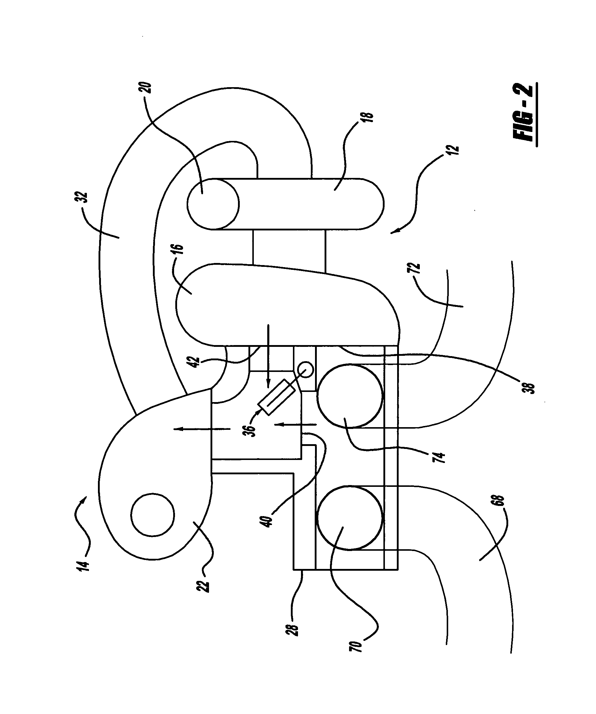
[0032]Referring to FIG. 1, a two-stage exhaust gas turbocharger unit is generally shown at 10, comprised of a high-pressure (HP) turbocharger unit 12, and a low-pressure (LP) turbocharger unit 14. The HP turbocharger unit 12 includes a HP turbine 16, and an HP compressor 18 having an outlet port 20. Similarly, the LP turbocharger unit 14 includes a LP turbine 22 and a LP compressor 24 having an outlet port 26. The LP turbine 22 is mounted on an exhaust manifold 28. The LP compressor 24 is connected to an intake line 30, which is connected at the center of LP compressor 24. An intake conduit 32 is connected to outlet port 26 on a first end, and is connected to the center of HP turbine 18 on a second end.

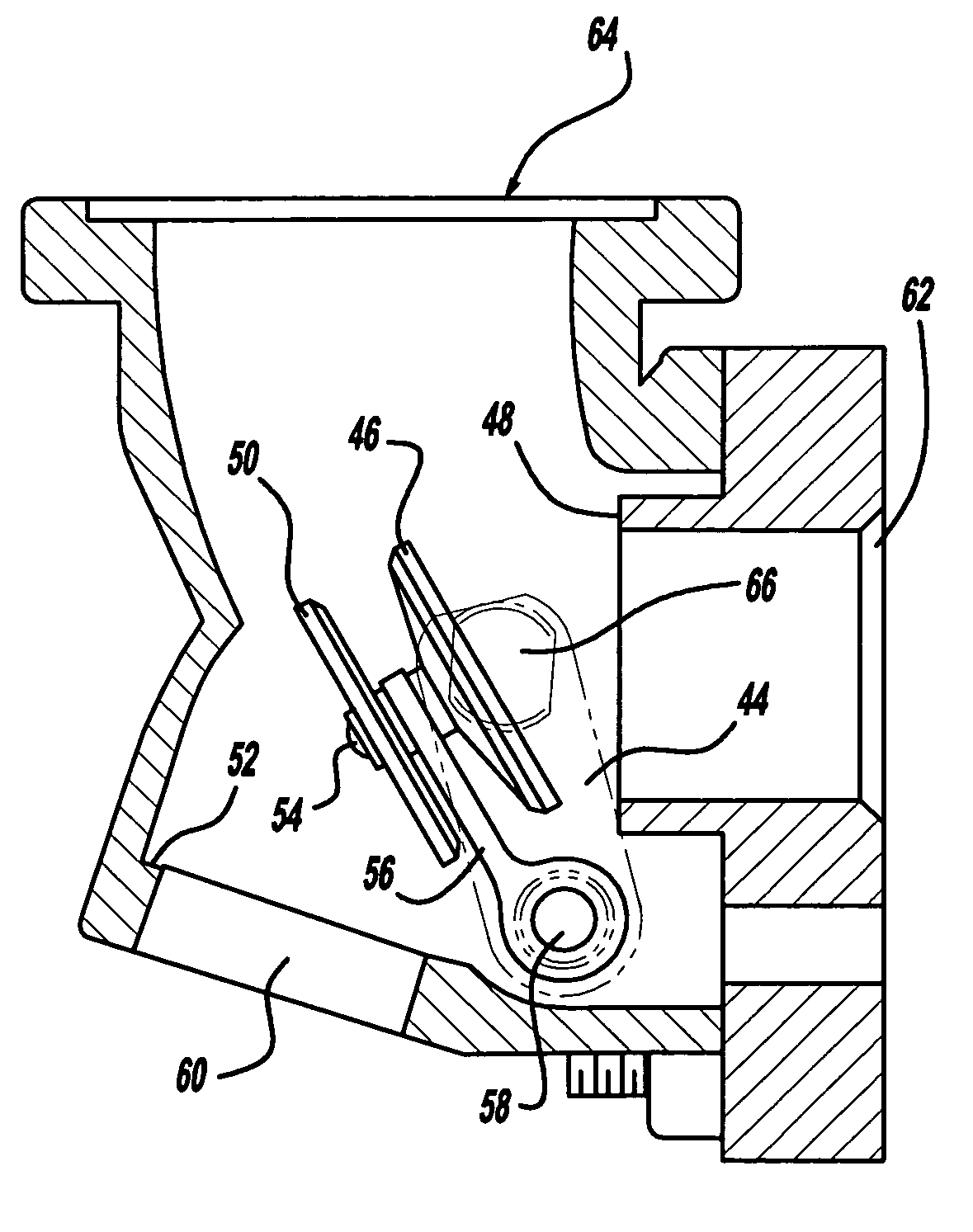
[0033]The HP turbine 16 and the LP turbine 22 are connected by a valve assembly 34 having a valve 36, shown in FIG. 1...


PUM

PropertyMeasurementUnit
circumferenceaaaaaaaaaa
pressureaaaaaaaaaa
speedsaaaaaaaaaa

Abstract

The present invention is directed to a bypass valve assembly having a valve housing with an inlet port, outlet port, and bypass port all formed within the valve housing. A valve member is operably connected to the valve housing and includes a first valve plate and second valve plate that face in substantially opposite directions from each other. The first valve plate articulates to form a tight barrier with the outlet port when the valve member is in a first position, and the second valve plate articulates to form a tight barrier with the bypass port when the valve member is in a second position.

Description

CROSS-REFERENCE TO RELATED APPLICATIONS[0001]This application is a continuation-in-part of U.S. Non-Provisional patent application Ser. No. 11 / 125,959 filed on May 10, 2005.FIELD OF THE INVENTION[0002]The present invention relates to a control valve for a motor vehicle, more specifically, a bypass valve assembly to selectively direct a fluid medium flow.BACKGROUND OF THE INVENTION[0003]Two-stage turbochargers are commonly known and are used in all kinds of engines. They consist of a high-pressure (HP) turbine, and a low-pressure (LP) turbine, with each turbine having its own compressor. The HP turbine is typically smaller than the LP turbine, and rotates at faster speeds. During normal operating conditions, when the engine runs at lower speeds, (such as at a stop light), the only turbine in use is the HP turbine. When the engine is running at lower speeds, it creates less exhaust gas energy. This lower amount of exhaust gas energy is not enough to power the larger, LP turbine, but i...

Claims


Application Information

Patent Timeline
Patent Type & Authority Applications(United States)
IPC IPC(8): F16K1/20B23P15/00
CPCF01D17/145Y10T29/49405F01N2240/36F01N2410/00F02B29/0418F02B37/001F02B37/002F02B37/004F02B37/007F02B37/013F02B37/18F02B37/183F02C6/12F02D9/04F02M25/0711F02M25/0719F02M25/0729F02M25/0796F16K11/052Y02T10/144F05D2220/40F01N13/10F02M26/08F02M26/16F02M26/26F02M26/71Y02T10/12
Inventor GRISSOM, THOMAS A.BUSATO, MURRAYTELEP, ROBERT J.
Owner BORGWARNER INC
Why Eureka
Try Eureka