Form fitting electric shaver with multiple cutting assemblies

a technology of electric shaving and assembly, applied in the direction of metal working devices, etc., can solve the problem of limiting the ability of shaver heads or foils to simultaneously cover a large surface area

Inactive Publication Date: 2009-01-29
CONAIR CORP
View PDF11 Cites 12 Cited by
  • Summary
  • Abstract
  • Description
  • Claims
  • Application Information

AI Technical Summary

Benefits of technology

[0006]It is an object of the present invention to provide an electric shaving device which can, simultaneously and with comfort, relatively closely shave portions of a relatively large surface area on the body such as, but not limited to, the human head.
[0008]Still another object of the invention is to reduce the extent to which a shaver head needs to deviate from its unbiased position in order to accommodate relatively curved surface portions to be shaved.
[0012]According to the present invention, an electric shaving device has a plurality of shaving foils mounted parallel to respective, for example, generally planar surfaces, where the surfaces are not parallel to each other. This presents an effective area to be shaved in a single stroke, as the plurality of foils are mounted, generally, at positions which allow them with a reasonable amount of angular deviation to be positioned tangentially to the curvature of the human head at different points across the length of the shaving head. Such positioning is accommodated by spring mounting the foils in an unbiased position which allows them to be biased into other positions by the application of pressure to the foils by the body part being shaved.

Problems solved by technology

This limits the ability of the shaver heads or foils to simultaneously cover a large surface area, when the surface to be shaved is convex, as is the case, for example, with the human scalp, particularly at the top of the head.
Shaving such body portions poses a particular challenge due to the substantial absence of a layer of fat underneath the skin, making the stability of the shaver heads to move conform to the shape of the scalp particularly important in view of the inability of the scalp to conform in shape to the form of the shaver.

Method used


Image

  • Form fitting electric shaver with multiple cutting assemblies
  • Form fitting electric shaver with multiple cutting assemblies
  • Form fitting electric shaver with multiple cutting assemblies

Examples


Embodiment Construction

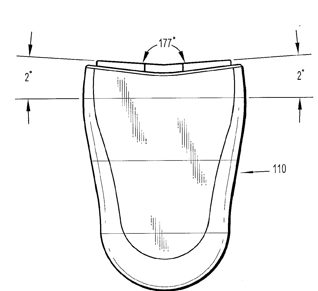
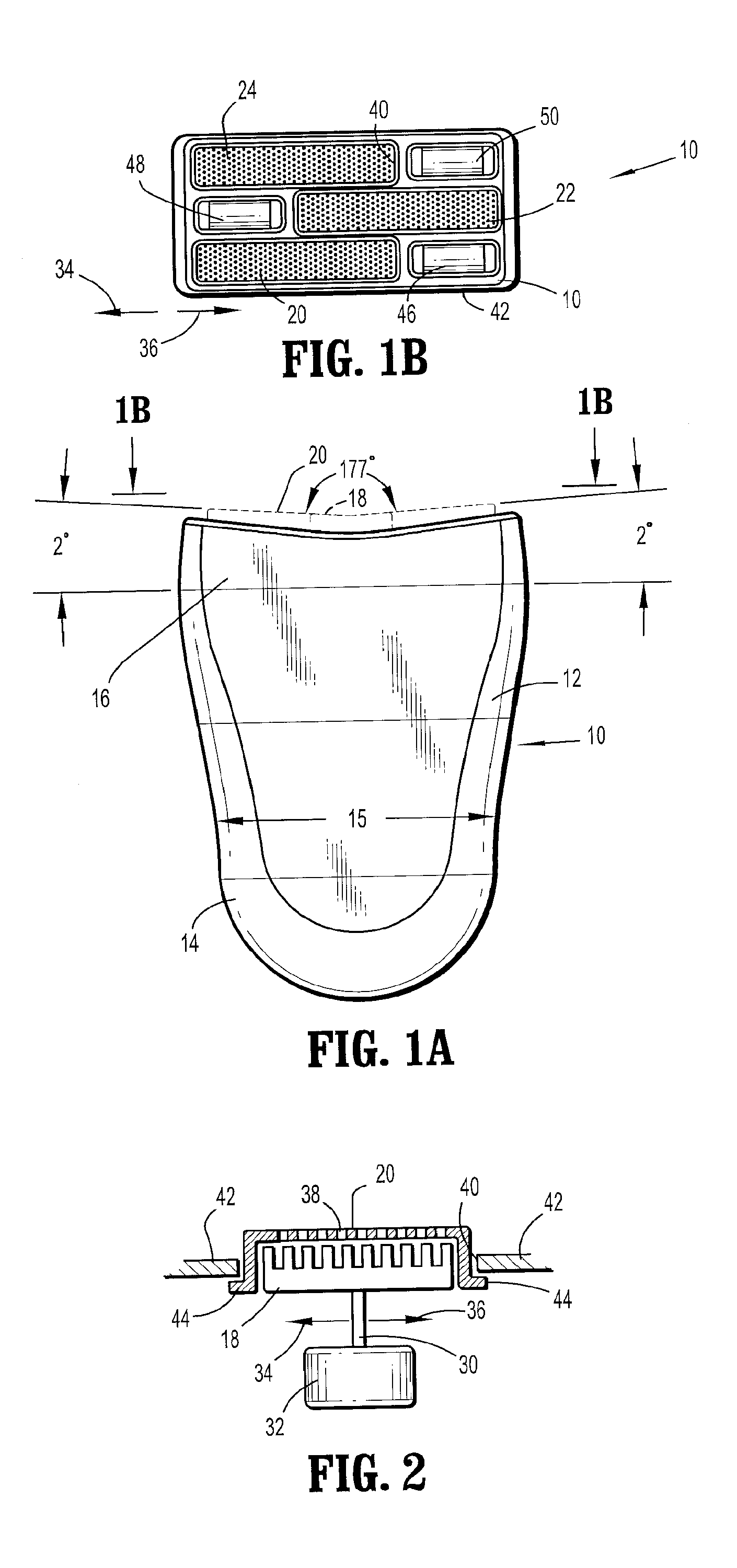
[0042]Referring to FIGS. 1A and 1B, a first embodiment of the present invention comprises an electric shaving device 10 which comprises a housing 12 with a handle portion 14. In accordance with a preferred embodiment, handle portion 14 on shaving device 10 is, optionally, of a smaller transverse dimension 15 as compared to head portion 16 to allow easy grasping of shaving device 10. In accordance with the preferred embodiment, handle portion 14 houses an electric motor, as well as drive components which are coupled to the electric motor. In accordance with a preferred embodiment, the motor is battery-powered, for example by a rechargeable battery.

[0043]The arrangement of the electric motor and drive components may be of any suitable type generally known in the art. Such subsystems may comprise an electric motor coupled to a cutting member 18, as illustrated in phantom lines in FIG. 1A. Cutting member 18 is positioned to bear against and conform to the shape of the inside surface of ...


PUM


Abstract

An apparatus for shaving a curved portion of the body, comprises an appliance body handle configured and dimensioned to be grasped by the hand of a user. Optionally, the support surface may define two planes with the shaving assembly lying in two planes and the planes being rotated with respect to each other with the rotation being along an axis extending in the direction of shaving. A support surface is disposed proximate to the appliance body handle, and it is secured to the appliance body handle. A first shaving member is floatingly mounted on the support surface at a first shaving member position and at a first shaving member angular orientation. A second shaving member is floatingly mounted on the support surface at a second shaving member position and at a second shaving member angular orientation.

Description

CROSS REFERENCE TO RELATED APPLICATIONS[0001]This application claims the benefit of Provisional Patent Application No. 60 / 961,736, filed 24 Jul. 2007, the disclosure of which is hereby incorporated herein by reference.BACKGROUND OF THE INVENTION[0002]1. Field of the Invention[0003]The invention relates to personal-care appliances and, more particularly, to electric powered shaving devices for shaving hair on curved parts of the body and particularly well adapted for shaving the head.[0004]2. Description of Related Art[0005]Various electric powered shaving devices exist in different forms for shaving various parts of the body, some having special characteristics for particularly effectively shaving specific parts of the body. Most commercially manufactured electric shavers today have floating heads or a convex shaped foil or contact assembly for shaving contoured body parts such as the chin or the legs. These shavers generally have a shaving assembly with a flat base to which the flo...

Claims


Application Information

Patent Timeline
Patent Type & Authority Applications(United States)
IPC IPC(8): B26B21/02
CPCB26B19/042
Inventor CARLUCCI, VITO JAMES
Owner CONAIR CORP
Why Eureka
Try Eureka