
Device for Improving the Charging or Discharging Process of a Battery

a technology for improving the charging or discharging process of batteries, applied in the direction of charging equalisation circuits, electric vehicles, electrical apparatus, etc., can solve the problem of balancing used on certain time intervals

Inactive Publication Date: 2009-01-29
BERNER FACHHOCHSCHULE FUR TECHN & INFORMATIK
View PDF11 Cites 77 Cited by
  • Summary
  • Abstract
  • Description
  • Claims
  • Application Information

AI Technical Summary

Benefits of technology

The present invention provides a device for monitoring a battery with multiple cells in series. The device uses a balanced scheme to keep the charge imbalance between the cells within a narrow band. This balanced scheme avoids the drawbacks of previous methods.

Problems solved by technology

The technical problem addressed in this patent is the need for improved balancing methods for charging and discharging batteries, as well as more accurate methods for determining the state of health or age of batteries.

Method used


Image

  • Device for Improving the Charging or Discharging Process of a Battery
  • Device for Improving the Charging or Discharging Process of a Battery
  • Device for Improving the Charging or Discharging Process of a Battery

Examples


Embodiment Construction

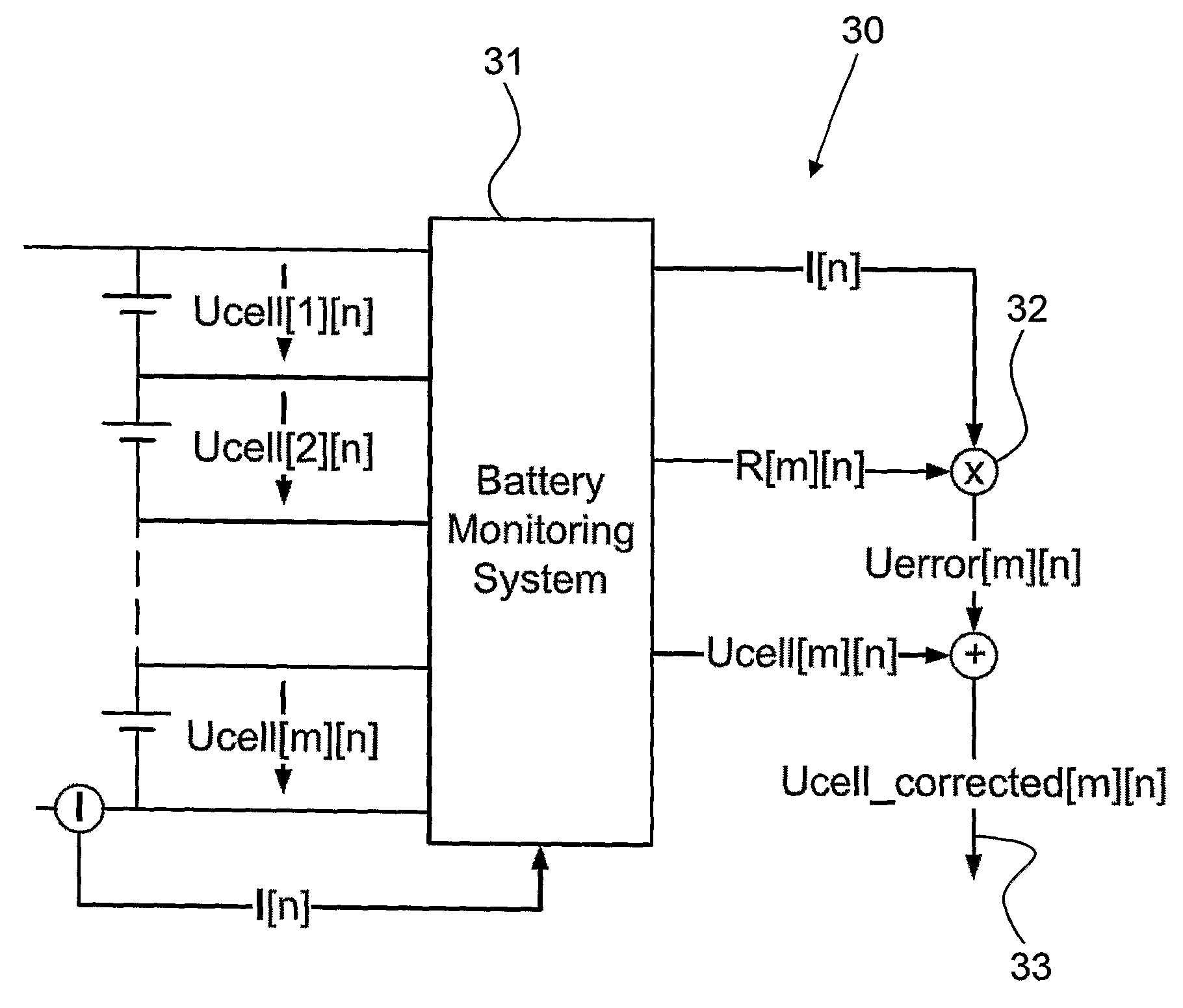
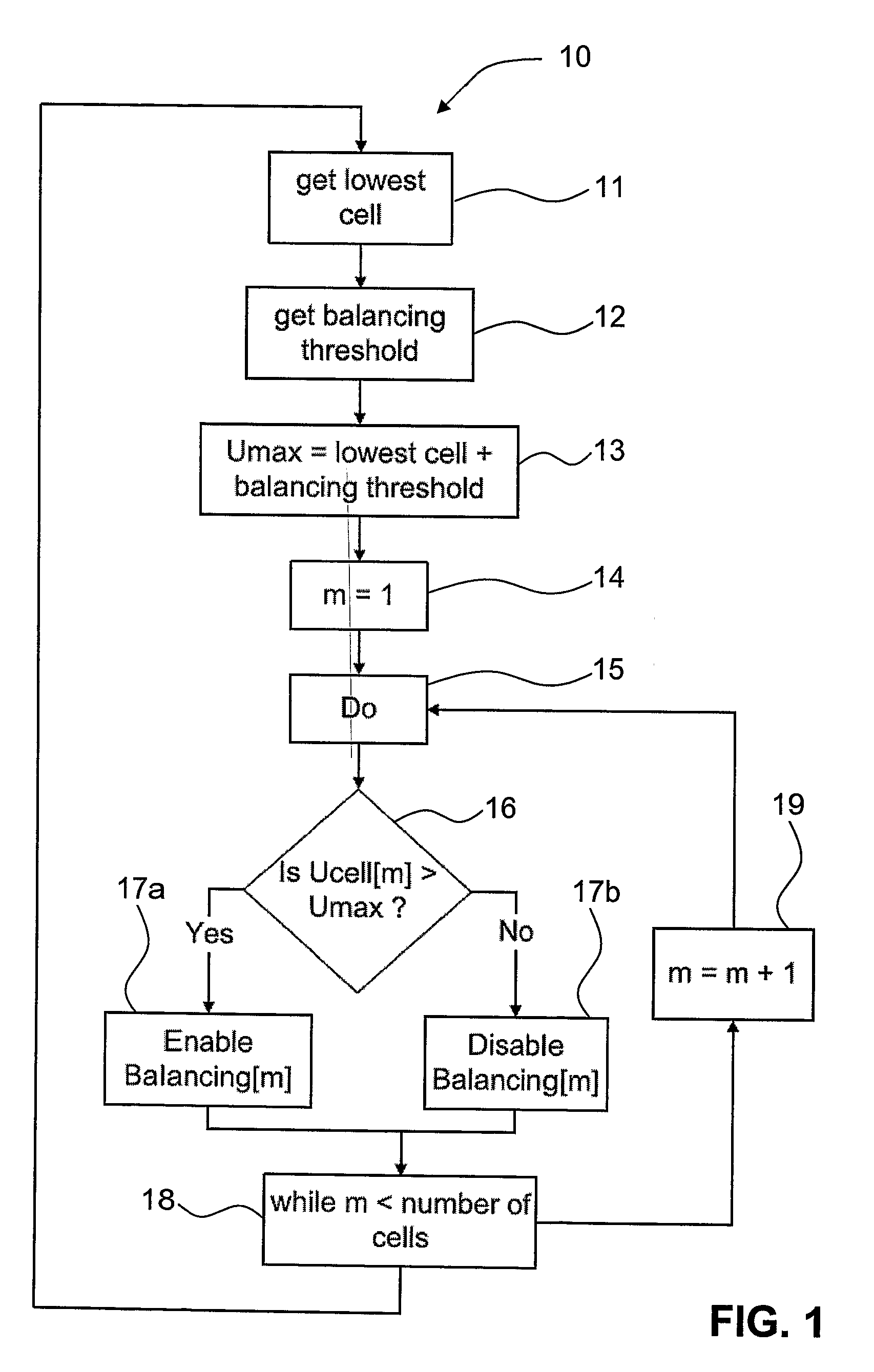
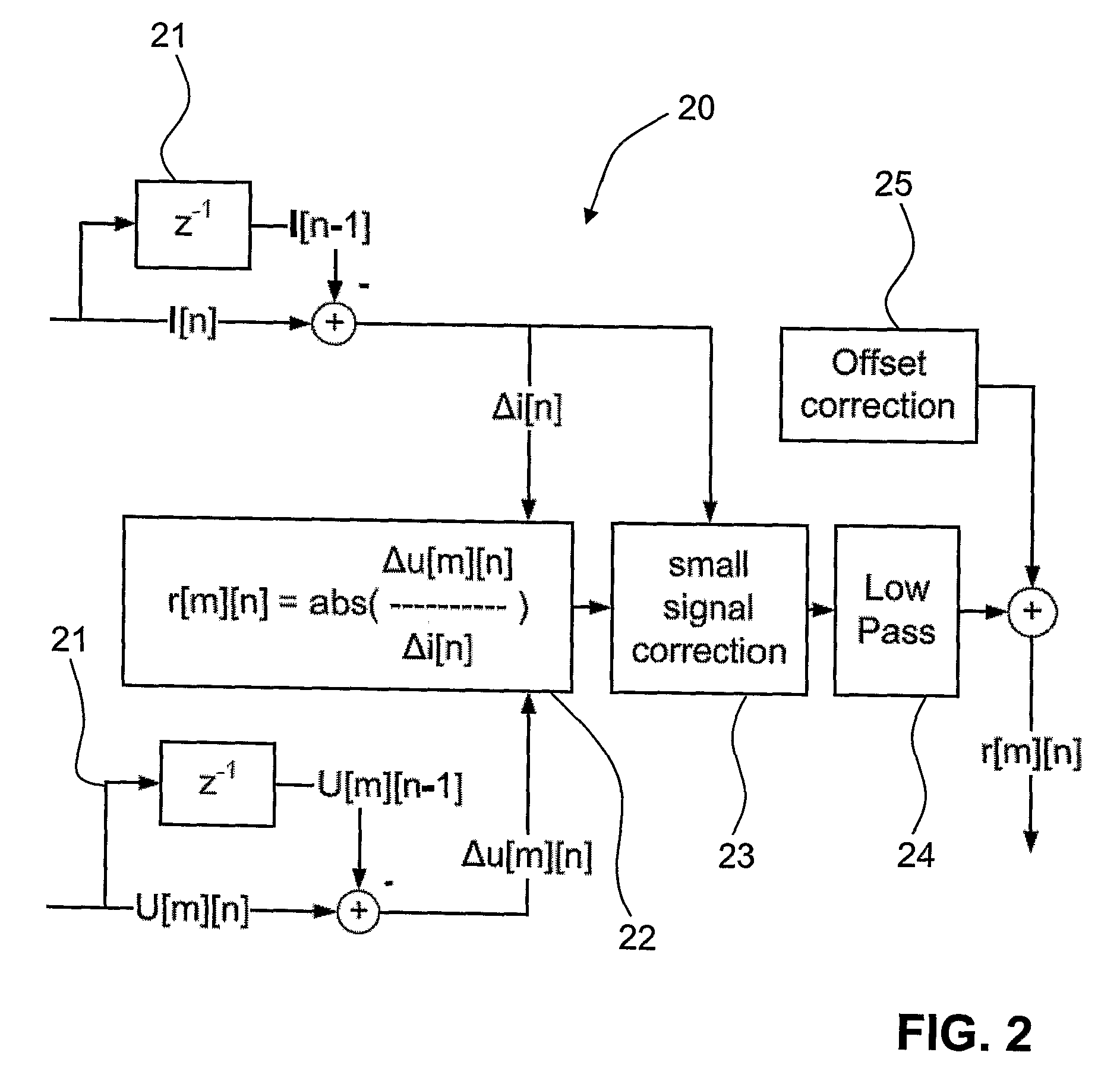
[0016]By means of the FIGS. 1 to 3 there is explained a preferred embodiment of the present invention, which is a monitoring and balancing device for multicell batteries. Very good results were achieved with a higher number of cells, where the probability of an imbalance of the cell charge is higher and an increase over time as some cells have either a lower quality or are differently exposed to the environment and the aging process is therefore faster. Such a multicell structure battery may be a lithium-ion, lithium polymer or any other energy storage cell that should be kept within certain charge operating limits or as an indicator operating limits. For the sake of simplicity, the term battery refers to such multicell structure batteries. Such batteries may be used in automotive applications (e.g. Hybrid-cars, fuel-cell cars, EV-cars, utility vehicles, scooters, e-bikes and the like), in mobile power supply applications (e.g. power tools, portable computers, embedded computers, me...


PUM


Abstract

A device for balancing a plurality of at least two batteries or cells of a multicell battery comprises a multicell battery and a battery management system with a balancing circuit. Thereby all individual battery cells are connected to the battery monitoring system, wherein the battery monitoring system measures single cell voltage as well as the battery temperature and the current. The battery monitoring system is able to discern the lowest cell voltage and to discern a number of cells having a voltage higher than a determined maximum allowable voltage, which will be balanced until the charge imbalance decreases to an acceptable amount. The battery management system is active during charging and discharging of the multicell battery and the thresholds vary with the state of the battery.

Description


Claims


Application Information

Patent Timeline
Owner BERNER FACHHOCHSCHULE FUR TECHN & INFORMATIK
Learn More