Developing system and image forming apparatus incorporating same

a development system and image forming technology, applied in the direction of electrographic process apparatus, instruments, optics, etc., can solve the problems of loss of print quality, insufficient delivery performance, and leakage of compressed air in the pneumatic path of such a developing system

Inactive Publication Date: 2009-01-29
RICOH KK
View PDF17 Cites 25 Cited by
  • Summary
  • Abstract
  • Description
  • Claims
  • Application Information

AI Technical Summary

Benefits of technology

[0016]In one exemplary embodiment, the image forming apparatus includes an electrophotographic system and a developing system. The electrophotographic system is configured to form an electrostatic latent image. The developing system includes a developing unit, a mixing container, a rotary feeder, an air pump, and an airflow regulator, and is configured to develop the electrostatic latent image. The developing unit is configured to convert a latent image into visible form using a developer. The mixing container is separated from the developing unit and is configured to hold and mix part of the developer after use. The rotary feeder is configured to dispense the developer from the mixing container to a delivery path. The air pump is configured to supply compressed air to deliver the dispensed developer to the developing unit through the delivery path. The airflow regulator is located where the rotary feeder connects to the delivery path, and is configured to prevent the compressed air from flowing toward the rotary feeder from the delivery path.

Problems solved by technology

When used in an environment with a high toner consumption / supply rate, the close interval between replenishment and development may result in insufficient mixing of the replenished developer, which eventually causes a loss of print quality, such as background smudging and / or toner scattering.
Occasionally, the pneumatic path in such a developing system suffers from leakage of compressed air where the delivery tube connects to the replenishing unit, i.e., a dispensing opening of the measuring feeder.
Such air leakage naturally causes a reduction in propelling pressure leading to insufficient delivery performance, and the compressed air leaking into the mixing container obstructs the flow of developer from the mixing container to the measuring feeder, resulting in reduction or variation in a particle dispensing rate of the measuring feeder.
Such rotary feeders can feed developer in a controlled and regulated manner, but often do not offer the reliable sealing required to prevent air leakage in the pneumatic delivery of particles.
A good sealing may be provided by forming the rotor blades of resilient material to fit tightly in the surrounding stator, which, however, seems impractical because rubbing the rotor blades against the stator wall will eventually cause significant degradation of the metering mechanism.
Moreover, the resilient blade configuration may not have satisfactory durability when used in a two-component developing system that handles hard carrier particles formed of iron and / or ferrite material.

Method used


Image

  • Developing system and image forming apparatus incorporating same
  • Developing system and image forming apparatus incorporating same
  • Developing system and image forming apparatus incorporating same

Examples


Embodiment Construction

[0027]In describing exemplary embodiments illustrated in the drawings, specific terminology is employed for the sake of clarity. However, the disclosure of this patent specification is not intended to be limited to the specific terminology so selected, and it is to be understood that each specific element includes all technical equivalents that operate in a similar manner and achieve a similar result.

[0028]Referring now to the drawings, wherein like reference numerals designate identical or corresponding parts throughout the several views, exemplary embodiments of the present patent application are described.

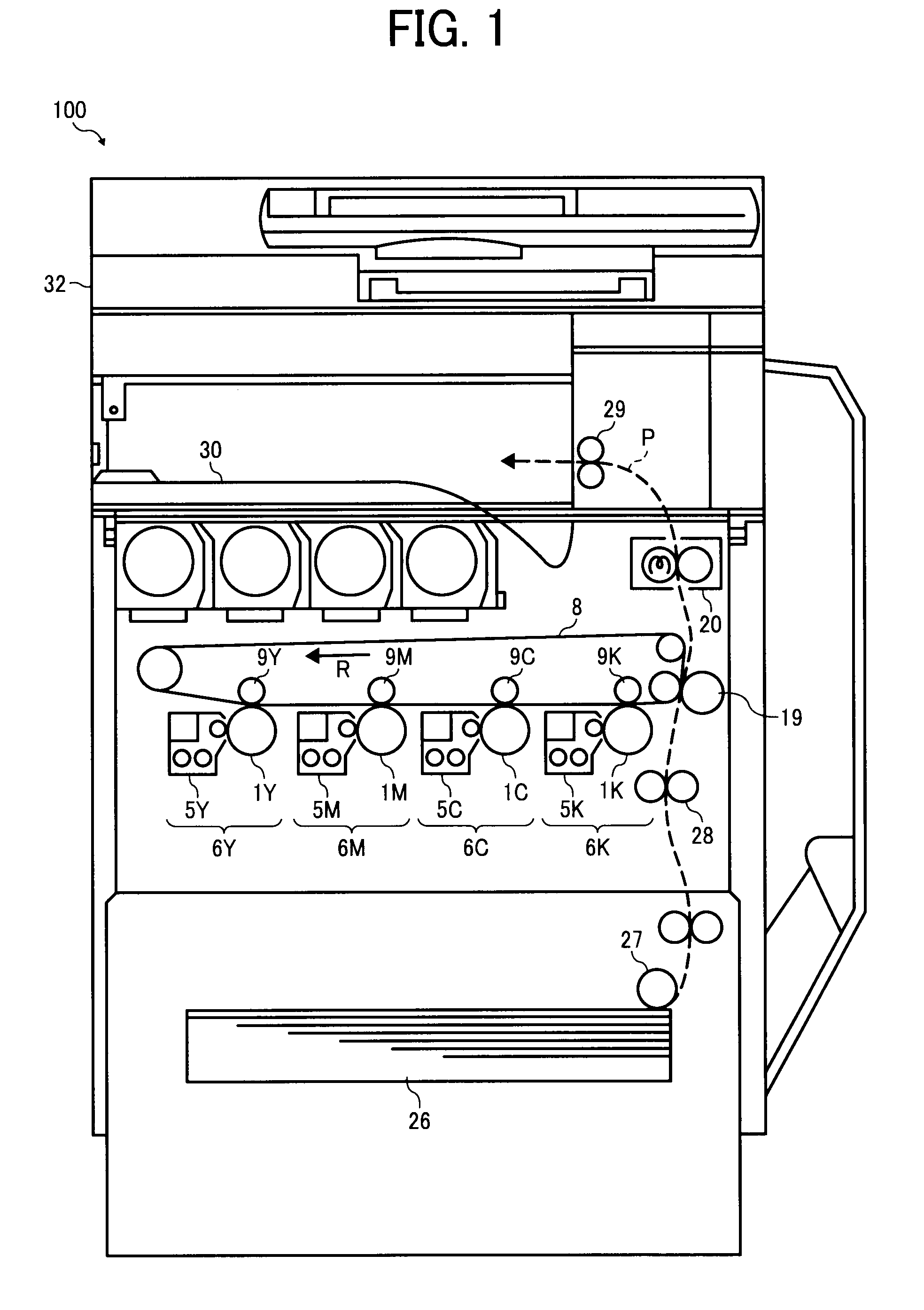
[0029]FIG. 1 is a schematic diagram illustrating an image forming apparatus 100 incorporating a developing system according to this patent specification.

[0030]As shown FIG. 1, the image forming apparatus 100 includes imaging units 6Y, 6M, 6C, and 6K featuring electrophotographic capabilities. The imaging units 6Y, 6M, 6C, and 6K each includes a photosensitive drum 1Y, 1M, 1C, an...


PUM


Abstract

A developing system includes a developing unit, a mixing container, a rotary feeder, an air pump, and an airflow regulator. The developing unit is configured to convert a latent image into visible form using a developer. The mixing container is separated from the developing unit and is configured to hold and mix part of the developer after use. The rotary feeder is configured to dispense the developer from the mixing container to a delivery path. The air pump is configured to supply compressed air to deliver the dispensed developer to the developing unit through the delivery path. The airflow regulator is located where the rotary feeder connects to the delivery path, and is configured to prevent the compressed air from flowing toward the rotary feeder from the delivery path.

Description

CROSS-REFERENCE TO RELATED APPLICATIONS[0001]The present patent application claims priority under 35 U.S.C. §119 from Japanese Patent Application No. 2007-196280 filed on Jul. 27, 2007, the entire contents of which are hereby incorporated by reference herein in their entirety.BACKGROUND OF THE INVENTION[0002]1. Field of the Invention[0003]The present invention relates to a developing system and an image forming apparatus incorporating same, and more particularly, to a developing system that develops an electrostatic latent image on a photoconductive surface using developer, and an image forming apparatus incorporating such a developing system.[0004]2. Discussion of the Background[0005]In many electrophotographic image forming apparatuses, such as photocopiers, printers, facsimiles, plotters, or multifunctional machines with electrophotographic capabilities, two-component developers formed of toner and carrier particles are widely used to develop a visible toner image from an electro...

Claims


Application Information

Patent Timeline
Patent Type & Authority Applications(United States)
IPC IPC(8): G03G15/08
CPCG03G2215/0802G03G15/0877G03G15/0879G03G21/105
Inventor MATSUMOTO, JUNICHIIWATA, NOBUOKATOH, NATSUMIOHMURA, TOMOYA
Owner RICOH KK
Why Eureka
Try Eureka