Medical in-line flow control clamp device

a technology of flow control and clamp device, which is applied in the direction of medical devices, intravenous devices, other medical devices, etc., can solve the problems of inconvenient or embarrassing use for patients, and the use of the clamp device is relatively easy to dislodg

Inactive Publication Date: 2009-01-29
GARCIA JR RAUL
View PDF3 Cites 23 Cited by
  • Summary
  • Abstract
  • Description
  • Claims
  • Application Information

AI Technical Summary

Benefits of technology

[0011]It is the object of this invention to provide a novel in-line flow control device for medical use of the character described.
[0012]Another object is to provide a medical in-line flow control device which will lay flat against an infusion tube to which it is attached for use in opening or closing an infusion tube.
[0013]Another object is to provide a medical flow control device for opening and closing an infusion tube which may be arranged along the longitudinal axis of the tube.
[0014]Another object is to provide a medical in-line flow control device which permits positive opening and closing of an infusion tube to which it may be attached.
[0015]Another object is to provide a medical in-line flow control device which inhibits unintentional opening or closing.
[0016]Another object is to provide a locking and unlocking lug for an in-line medical flow control device.

Problems solved by technology

While these and other variations of these flow control devices for flexible plastic tubes used for delivering fluid to or removing fluid from a patient, all these known or conventional devices have a mass substantially larger than the fluid tube, and where the patent is ambulatory or dressed, the clamp shows through the patient's garment and its use is inconvenient or embarrassing for the patient or relatively easy to dislodge.

Method used


Image

  • Medical in-line flow control clamp device
  • Medical in-line flow control clamp device
  • Medical in-line flow control clamp device

Examples


Embodiment Construction

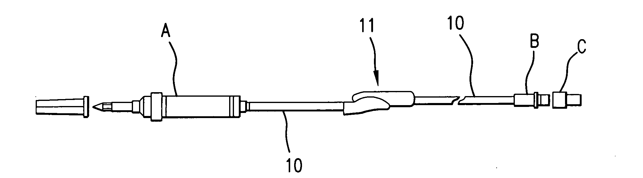
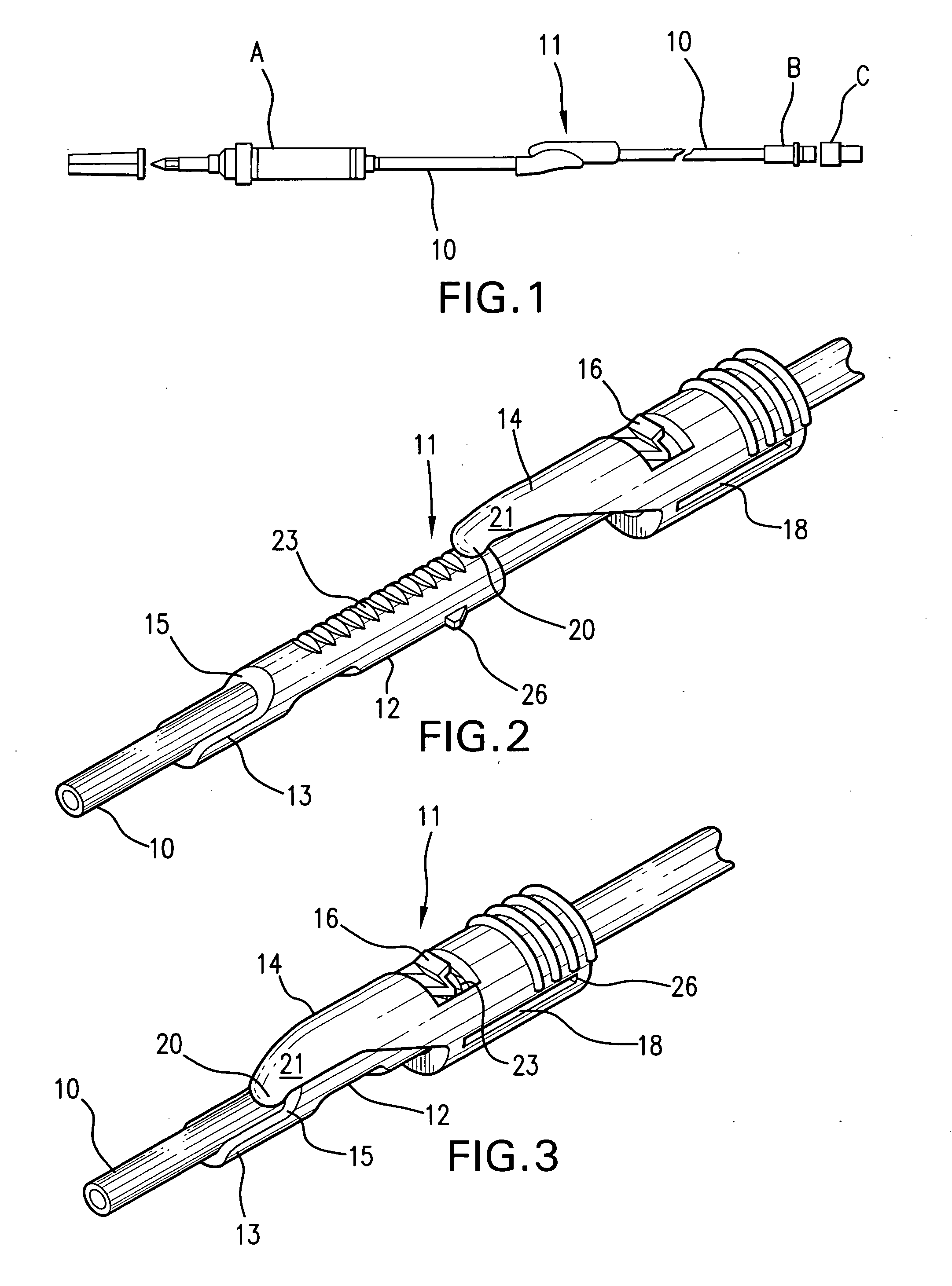
[0032]With reference to FIG. 1, a typical use of a flow control device embodying the present invention is in an intravenous administration set which may include a IV chamber A, an infusion tube 10, a clamp 11, a slip B and a cap C. Similar arrangements of a tube 10 and clamp 11 may be used in transfusion sets or in other programs for delivering medicament to or withdrawing fluid from a patient. The clamp 11 may be opened to permit flow of medicament or fluid through the tube 10 or closed to prevent flow. Similar arrangements are used in withdrawing fluid from the body of the patient, in which case the tube 10 is opened to permit flow and closed when a tube must be changed or other action is required. A Clamp 11 embodying the present invention may be utilized on tubes in all environments which presently use conventional roller clamps or foldable or static clips or clamps.

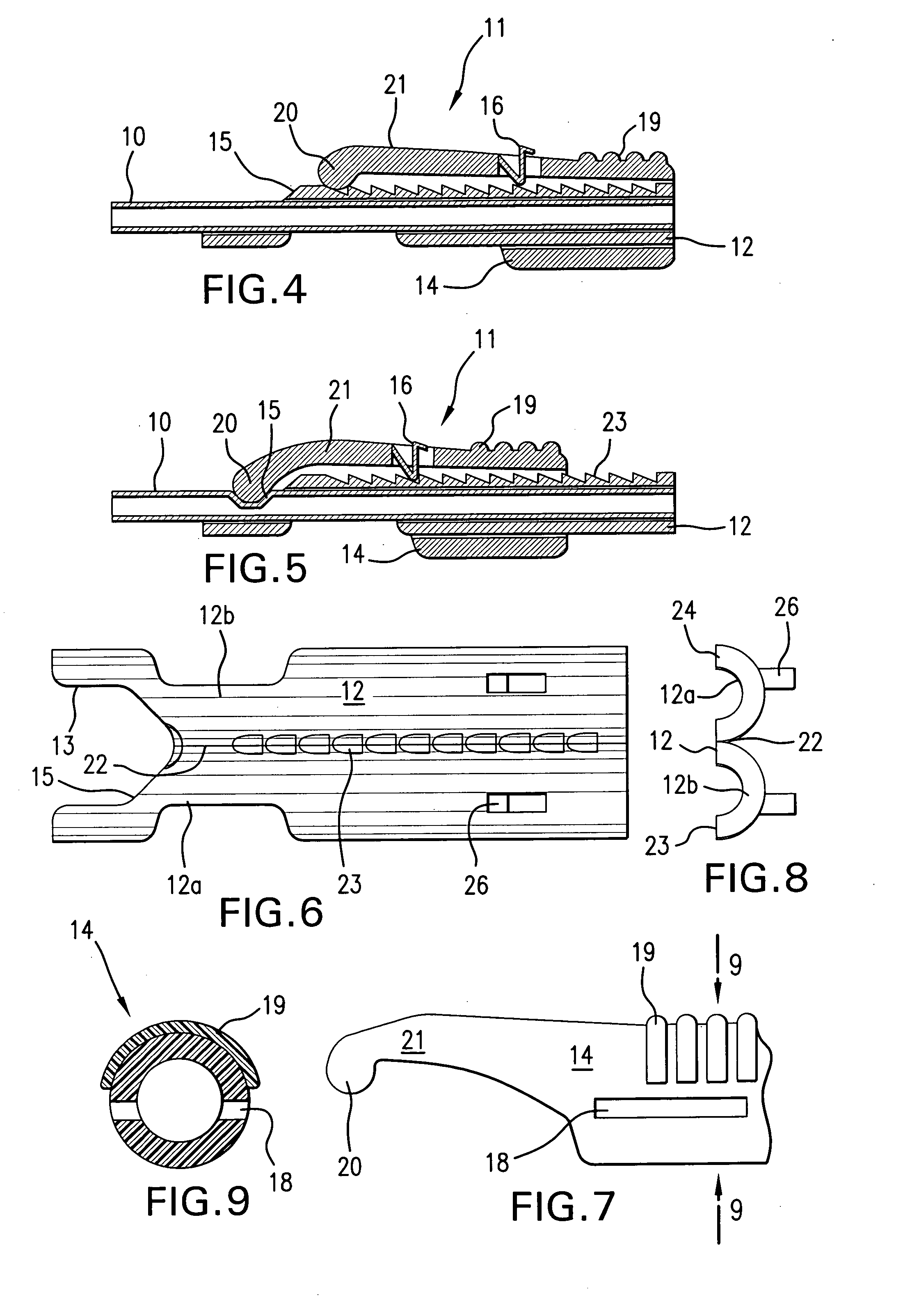
[0033]Preferably, flow control devices embodying the present invention are constructed from plastic material, such...


PUM


Abstract

A medical in-line flow control clamp device which is arranged coaxially along the longitudinal axis of an infusion tube or the like, and which has a sleeve connected to the tube and a slide having an arm movably mounted on and having a part biased toward the sleeve in a manner where the arm bears against and pinches the tube when the slid is moved relative to the sleeve. The sleeve may have a ramp and support directed toward the tube which causes the arm to move against the tube. The slide may be fabricated from a plastic material, such as acrylic, which causes the arm to bind against the tube. The sleeve may have one or more stops and latch means to receive and secure the arm in tube pinching relation. The sleeve and slide may have a track and projection parts which train the slide in a predetermined direction toward the tube as the slide is moved to pinching position on the sleeve. Bars may be arranged on the slide transverse to the sleeve and tube for manipulating the slide on the sleeve by finger pressure. The sleeve may be fabricated in portions connected by a web so they may be folded and held around the tube in a selected position.

Description

PRIORITY CLAIM[0001]Priority is claimed based upon U.S. Provisional Patent Application Ser. No. 60 / 962,252, MEDICAL IN-LINE FLOW CONTROL CLAMP DEVICE, filed Jul. 5, 2007.MEDICAL IN-LINE FLOW CONTROL CLAMP DEVICE[0002]This invention relates to medical in-line flow control devices, and is more particularly concerned with such devices having the capability to regulate flow of fluid in a tube used for medical purposes, and a device which is not substantially enlarged as to encumber the appearance or mobility of the persons requiring delivery of fluid through or from the tube.BACKGROUND AND SUMMARY OF THE INVENTION[0003]Most conventional flow control devices are of one of several types:[0004]1. Large one piece clips or clamps, exemplified by those shown in Flynn U.S. Pat. Nos. 4,673,161 or 4,588,160, which have been refined over the years with various locking arrangements, as in Guala et al U.S. Pat. No. 6,161,812 and US Patent Application 2006 / 0079849[0005]2. Devices which clamp a tube ...

Claims


Application Information

Patent Timeline
Patent Type & Authority Applications(United States)
IPC IPC(8): A61M5/00
CPCA61M39/284A61M2205/59A61M39/286
Inventor GARCIA, JR., RAUL
Owner GARCIA JR RAUL
Why Eureka
Try Eureka