Supercharge Your Innovation With Domain-Expert AI Agents!

Check valves with hinge shafts retained by bushings

a technology of hinge shaft and check valve, which is applied in the field of check valves, can solve the problems of exacerbated problems and conventional check valves can encounter problems

Inactive Publication Date: 2009-02-05
HONEYWELL INT INC
View PDF29 Cites 7 Cited by
  • Summary
  • Abstract
  • Description
  • Claims
  • Application Information

AI Technical Summary

Benefits of technology

The patent text describes a check valve with a valve body, hinge shaft, bushing, and closure element. The hinge shaft is secured to the valve body using a pin and a bushing with a groove for the pin. This prevents movement of the hinge shaft and bushing in a longitudinal direction. The technical effect of this design is improved stability and reliability of the check valve.

Problems solved by technology

Conventional check valves can encounter problems because the hinge shaft may loosen and migrate out of the valve body.
This issue is exacerbated by the high temperature and vibration environments of many types of check valves, particularly where there is a clearance between the valve body and the walls of the conduit in which it is mounted.

Method used


Image

  • Check valves with hinge shafts retained by bushings
  • Check valves with hinge shafts retained by bushings
  • Check valves with hinge shafts retained by bushings

Examples


Embodiment Construction

[0015]The following detailed description is merely exemplary in nature and is not intended to limit the invention or the application and uses of the invention. Furthermore, there is no intention to be bound by any theory presented in the preceding background or the following detailed description.

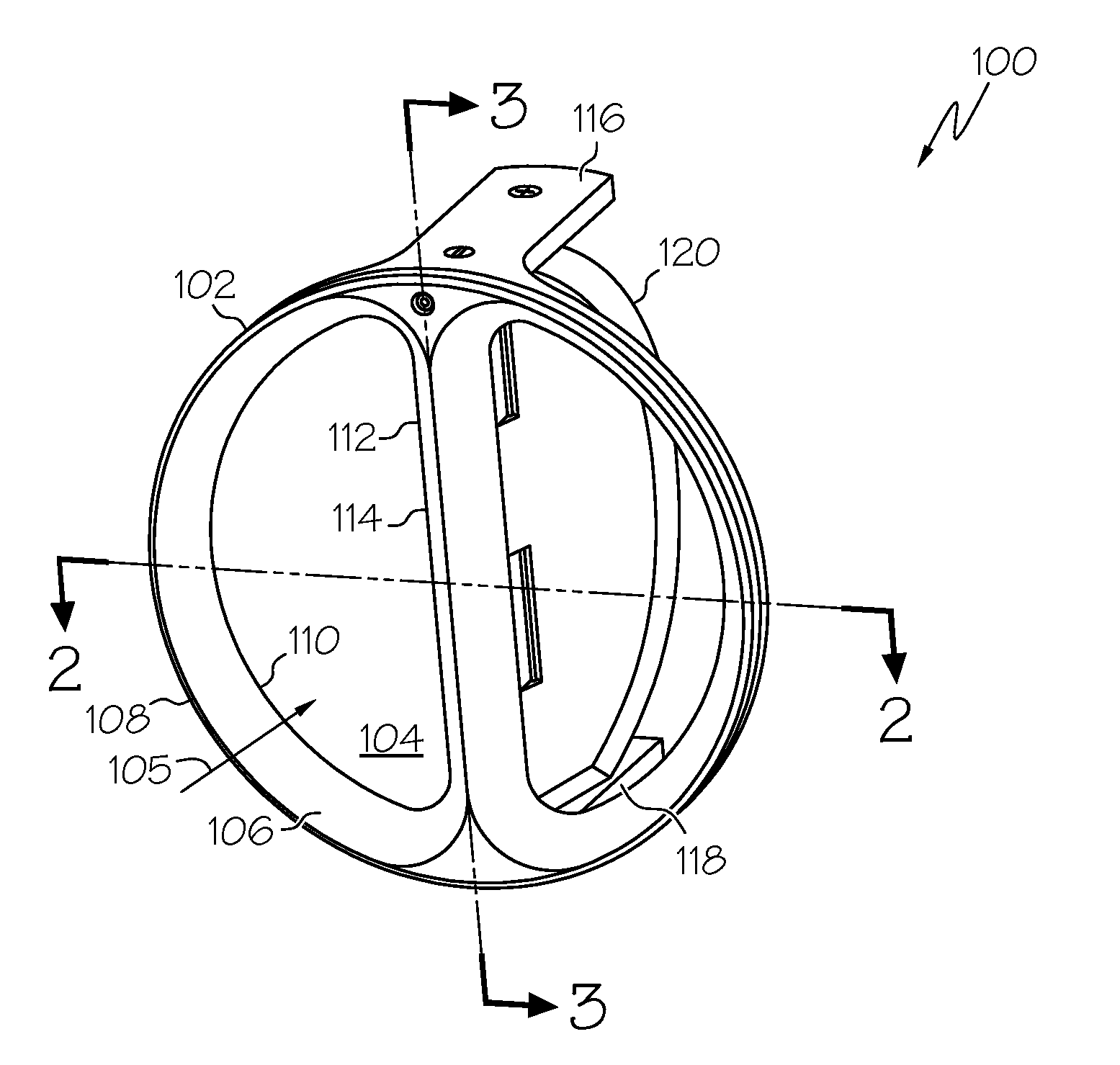
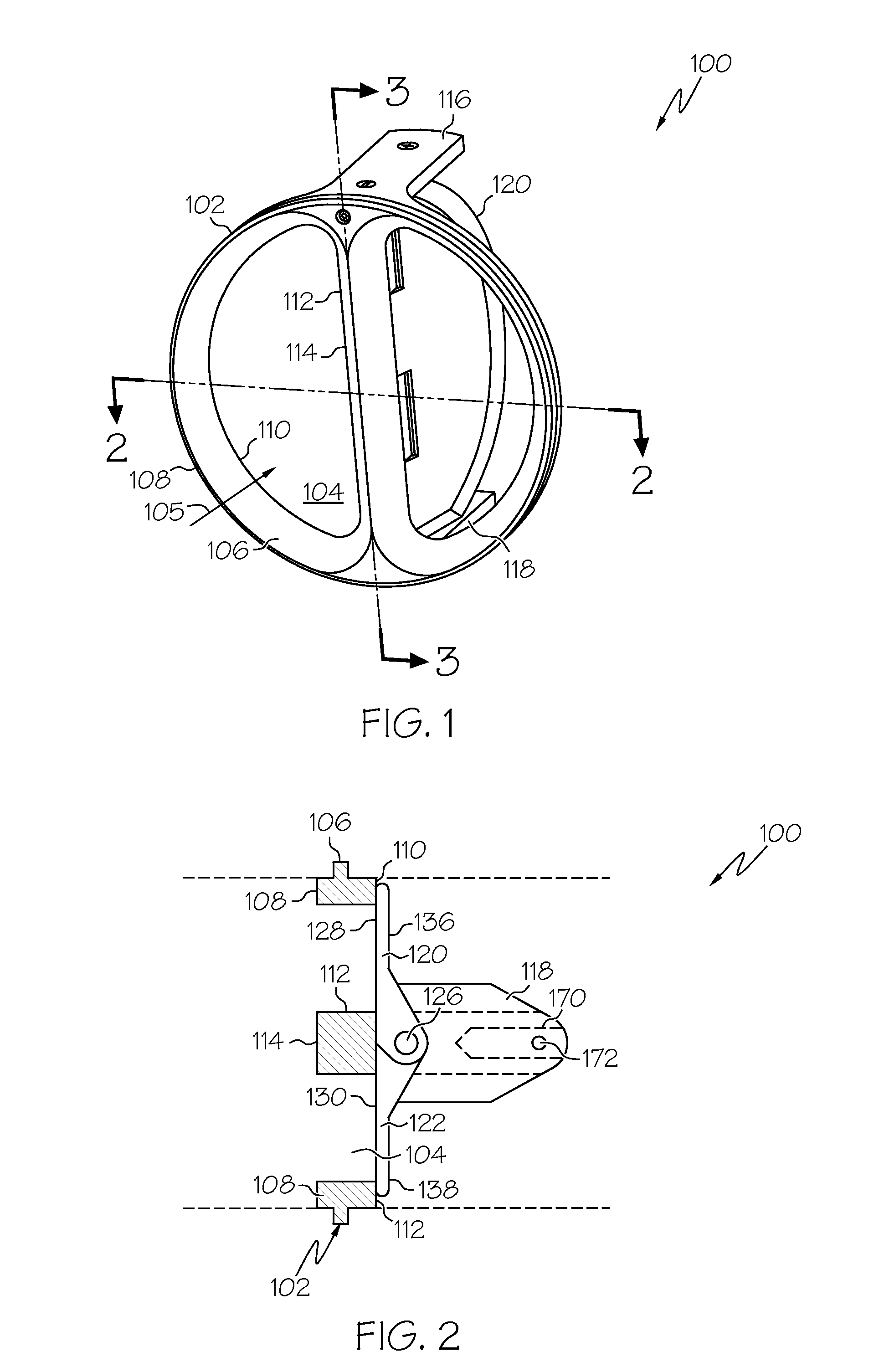
[0016]FIG. 1 is an isometric view of a check valve 100 in accordance with an exemplary embodiment. The check valve 100 includes a valve body 102 having an annular configuration defining a central flow passage 104. The valve body 102 can be coupled to or within a pipe or conduit (not shown) to enable fluid flow into the pipe or conduit through the flow passage 104 in direction 105. As will be discussed in further detail below, the check valve 100 is urged open by fluid flowing in the direction 105 while preventing fluid from flowing out of the check valve 100 in an opposite direction.

[0017]The valve body 102 has an annular flange 106 that defines the flow passage 104 and that includes an upst...


PUM


Abstract

Methods and apparatus are provided for retaining a hinge shaft of a check valve with a bushing. The check valve includes a valve body defining a flow passage therethrough; a hinge shaft; a bushing coupling the hinge shaft to the valve body; a pin secured to the valve body and engaging the bushing; and a closure element pivotally mounted on the hinge shaft for opening and closing the flow passage.

Description

[0001]This invention was made with Government support under Contract Number N00019-02-C-3002 of the Joint Strike Fighter Program. The Government has certain rights in this inventionTECHNICAL FIELD[0002]The present invention generally relates to check valves with flapper closure elements, and more particularly relates to methods and apparatus for retaining the hinge shaft on which the closure elements of check valves are pivotally mounted.BACKGROUND[0003]Check valves with flapper (or “wafer”) type closure elements are utilized in many industries. The check valves are typically mounted in pipes or other such conduits enable fluid flow in one direction and prevent fluid flow in the opposite direction. The closure elements of the check valve are pivotally mounted on a hinge shaft and can be biased closed by a resilient element such as a hinge spring. The hinge shaft is typically mounted by press fitting the ends of the hinge shaft in through holes formed in a valve body. The valve body ...

Claims


Application Information

Patent Timeline
Patent Type & Authority Applications(United States)
IPC IPC(8): F16K15/00
CPCF16K15/038Y10T137/0491Y10T137/7898
Inventor DULAY, RALPH L.KOLIC, MICHAELSUGAI, MAUREENTORNQUIST, DAVID B.ATKINS, DON J.
Owner HONEYWELL INT INC
Features
  • R&D
  • Intellectual Property
  • Life Sciences
  • Materials
  • Tech Scout
  • Unparalleled Data Quality
  • Higher Quality Content
  • 60% Fewer Hallucinations
Learn More