Air Recirculation in a Blow Molding Process

a technology of air recirculation and blow molding, which is applied in auxillary shaping apparatuses, other domestic items, manufacturing tools, etc., can solve the problems of high consumption of blowing media, increased structural complexity, and inability to accurately regulate the pre-blowing pressure, etc., and achieve the effect of shortening the switching time of the reversing mechanism

Active Publication Date: 2009-02-12
KRONES AG
View PDF4 Cites 8 Cited by
  • Summary
  • Abstract
  • Description
  • Claims
  • Application Information

AI Technical Summary

Benefits of technology

[0014]The low-pressure air supply and/or the low-pressure air media storage mechanism contains an element for determining the pressure, said element being connected to a control and regulating unit and supplying this unit with data about the actual pressure status. If the control and regulating unit recognizes, based on the signal received by the element for determining the pr

Problems solved by technology

These methods and devices are characterized by very high consumption of blowing media because they work with pressures of up 40 bar.
This device has the disadvantage that it requires an increased structural complexity.
Furthermore, with this device only inaccurate regulation of the pre-blowing pressure is possible.
Furthermore, this unexamined patent specification also discloses a device that operates according to this method.
The aforementioned devices and methods have disadvantages, however

Method used


Image

  • Air Recirculation in a Blow Molding Process
  • Air Recirculation in a Blow Molding Process
  • Air Recirculation in a Blow Molding Process

Examples


Embodiment Construction

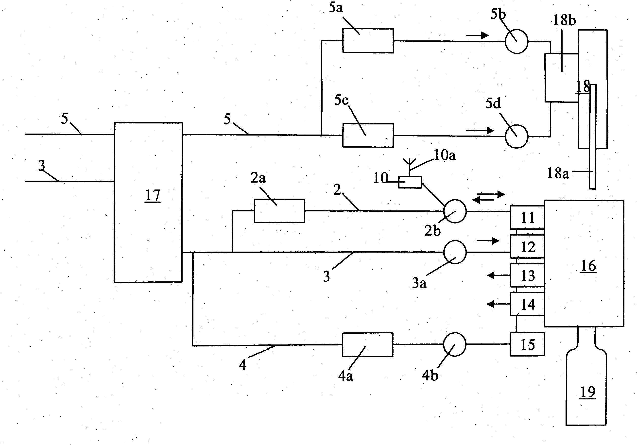
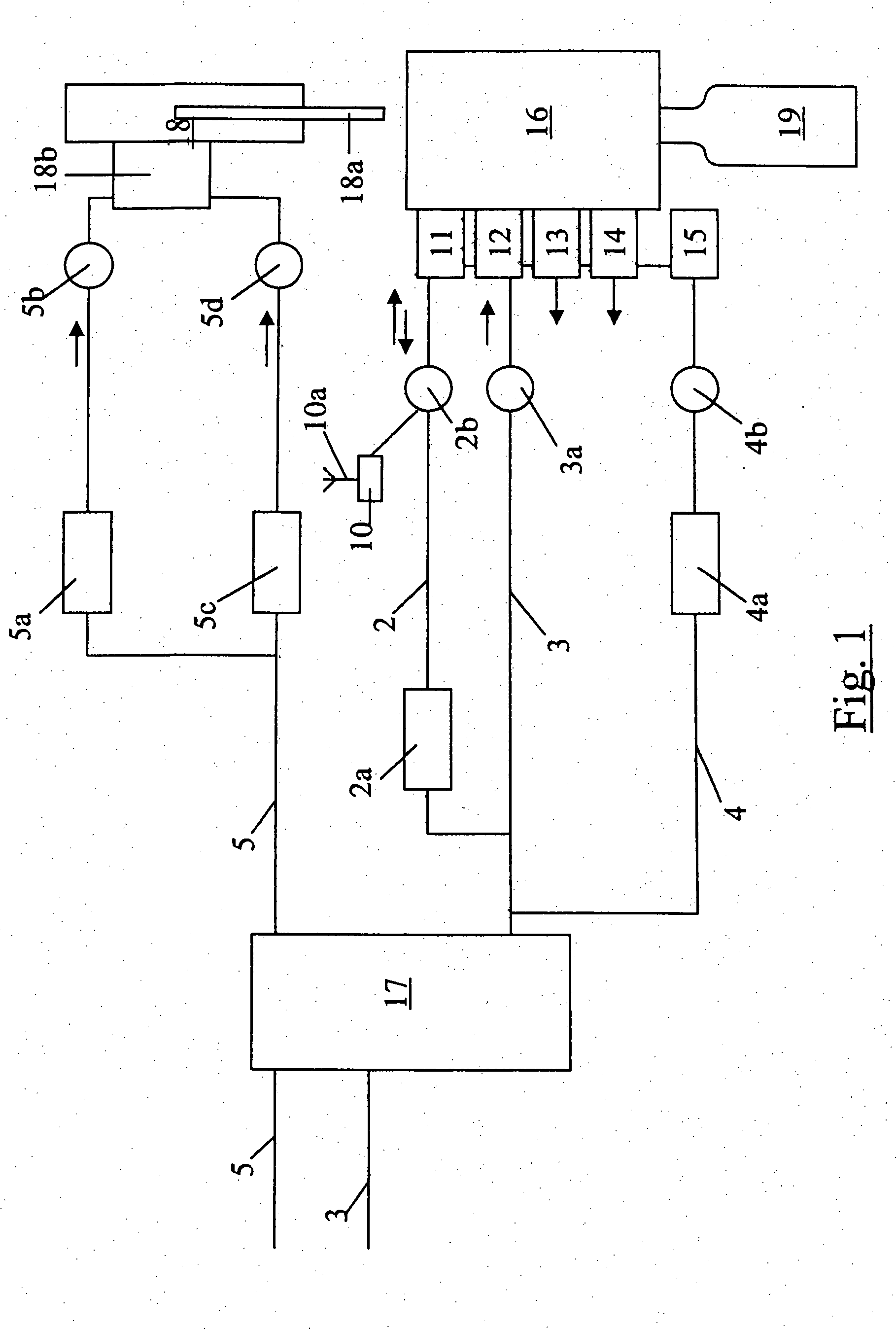
[0019]FIG. 1 shows an air distributor 17 with an inlet for a low-pressure air supply 5 and an inlet for a high-pressure blowing air supply 3. In the direction of the machine, the air distributor 17 has two outlets for the low-pressure air and the high-pressure air. The air distributor 17 has the task of bringing the blowing air from a stationary part of the machine into the rotating part of the machine. Downstream from the air distributor 17, the high-pressure blowing air is divided among three lines (2, 3, 4). The high-pressure blowing air distributed at 40 bar, for example, by the air distributor 17 into the three lines flows in line 2 first through a pressure regulator 2a that reduces the pressure to 16 bar, for example. Then the air flows further into a low-pressure media storage mechanism 2b which is designed here as a ring line. The pressure in this storage mechanism 2b is monitored by a pressure pickup 10. From the low-pressure media storage mechanism 2b, the air flows throug...


PUM

PropertyMeasurementUnit
Pressureaaaaaaaaaa
Moldableaaaaaaaaaa

Abstract

A device for molding a container from a thermoplastic material in which a heated parison is pre-blown by supplying low-pressure blowing air from a low-pressure air supply and then the blow molding is completed by subsequent supply of high-pressure blowing air and in which the high-pressure blowing air flowing out of the container that has been completely blow molded is supplied to the low-pressure air supply via a reversing mechanism during a transitional phase. A pressure monitoring is performed in the area of the low-pressure air supply and in which, after the transitional phase, the container is vented with respect to an ambient pressure whereby the pressure in the low-pressure air supply is controlled by varying the duration of the transitional phase.

Description

CROSS-REFERENCE TO RELATED APPLICATION[0001]This is the U.S. national stage under 35 U.S.C. § 371, of international application no. PCT / EP2005 / 009222, having an international filing date of Aug. 26, 2005, and claims priority to German application no. 10 2004 041 973.6 filed on Aug. 31, 2004.FIELD OF THE DISCLOSURE[0002]The invention relates to a method and device for air recirculation used in blow molding operations for containers, such as beverage bottles.BACKGROUND OF THE DISCLOSURE[0003]Such methods and devices are used especially for molding containers such as canisters or bottles. They are used in particular in the stretch blow molding technique where bottles and the like are manufactured for the food industry and especially for the beverage industry. These methods and devices are characterized by very high consumption of blowing media because they work with pressures of up 40 bar. Therefore, there will be repeated attempts to utilize the blow molding media as optimally as poss...

Claims


Application Information

Patent Timeline
IPC IPC(8): B29C49/78
CPCB29C33/424B29C49/06B29C49/12B29C49/4289B29C49/783B29C2049/1257B29C2049/1271B29C49/36Y02P70/10B29C49/1222B29C49/1229B29C49/42855B29C2949/0715B29C2049/7831B29C2049/7832B29C2049/7833B29C2049/78815
Inventor FINGER, DIETERASBRAND, HELMUT
Owner KRONES AG
Why Eureka
Try Eureka