Switching Power Supply and its Control Circuit, and Electronic Apparatus Employing Such Switching Power Supply

a technology of switching power supply and control circuit, which is applied in the direction of electric variable regulation, process and machine control, instruments, etc., can solve the problems of long time required to reach the desired voltage, affecting the reliability of the elements constructing the circuit, etc., and achieve the effect of shortening the time for generating a sufficiently high voltage for driving the light emitting elemen

Active Publication Date: 2008-06-12
ROHM CO LTD
View PDF2 Cites 45 Cited by
  • Summary
  • Abstract
  • Description
  • Claims
  • Application Information

AI Technical Summary

Benefits of technology

[0022]In the embodiment, time for generating a sufficiently high voltage for driving the light emitting element can be shortened.

Problems solved by technology

In the case of abruptly increasing the output voltage, inrush current may be generated or output voltage may become too high due to overshooting or ringing of the output voltage and thereby influencing the reliability of elements constructing the circuit.
There has been a problem when a load requiring a very high voltage of about hundreds V is connected to an output terminal of the switching power supply, time required to reach a desired voltage is long.

Method used


Image

  • Switching Power Supply and its Control Circuit, and Electronic Apparatus Employing Such Switching Power Supply
  • Switching Power Supply and its Control Circuit, and Electronic Apparatus Employing Such Switching Power Supply
  • Switching Power Supply and its Control Circuit, and Electronic Apparatus Employing Such Switching Power Supply

Examples


Embodiment Construction

[0031]The invention will now be described based on preferred embodiments which do not intend to limit the scope of the present invention but exemplify the invention. All of the features and the combinations thereof described in the embodiment are not necessarily essential to the invention.

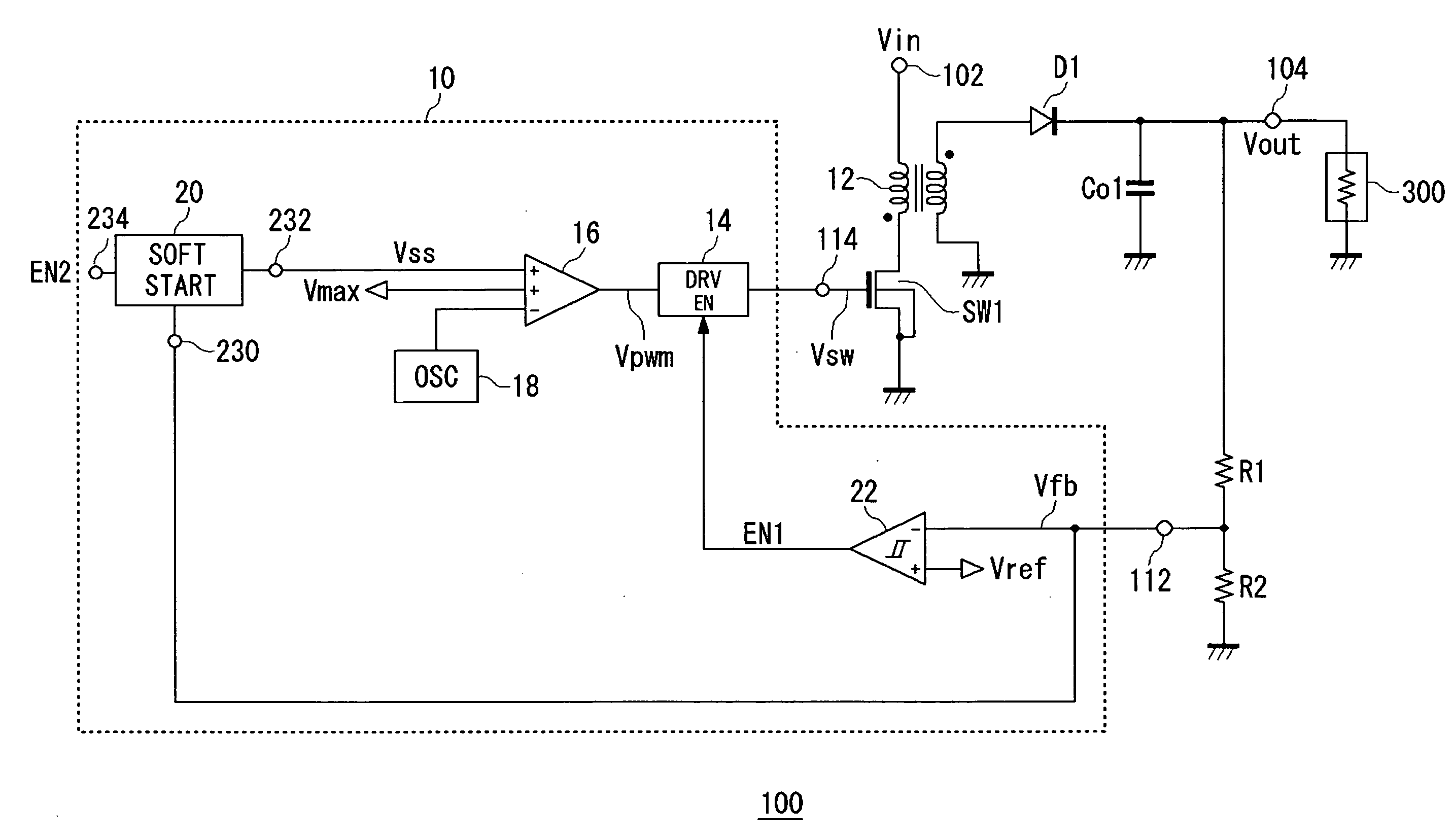
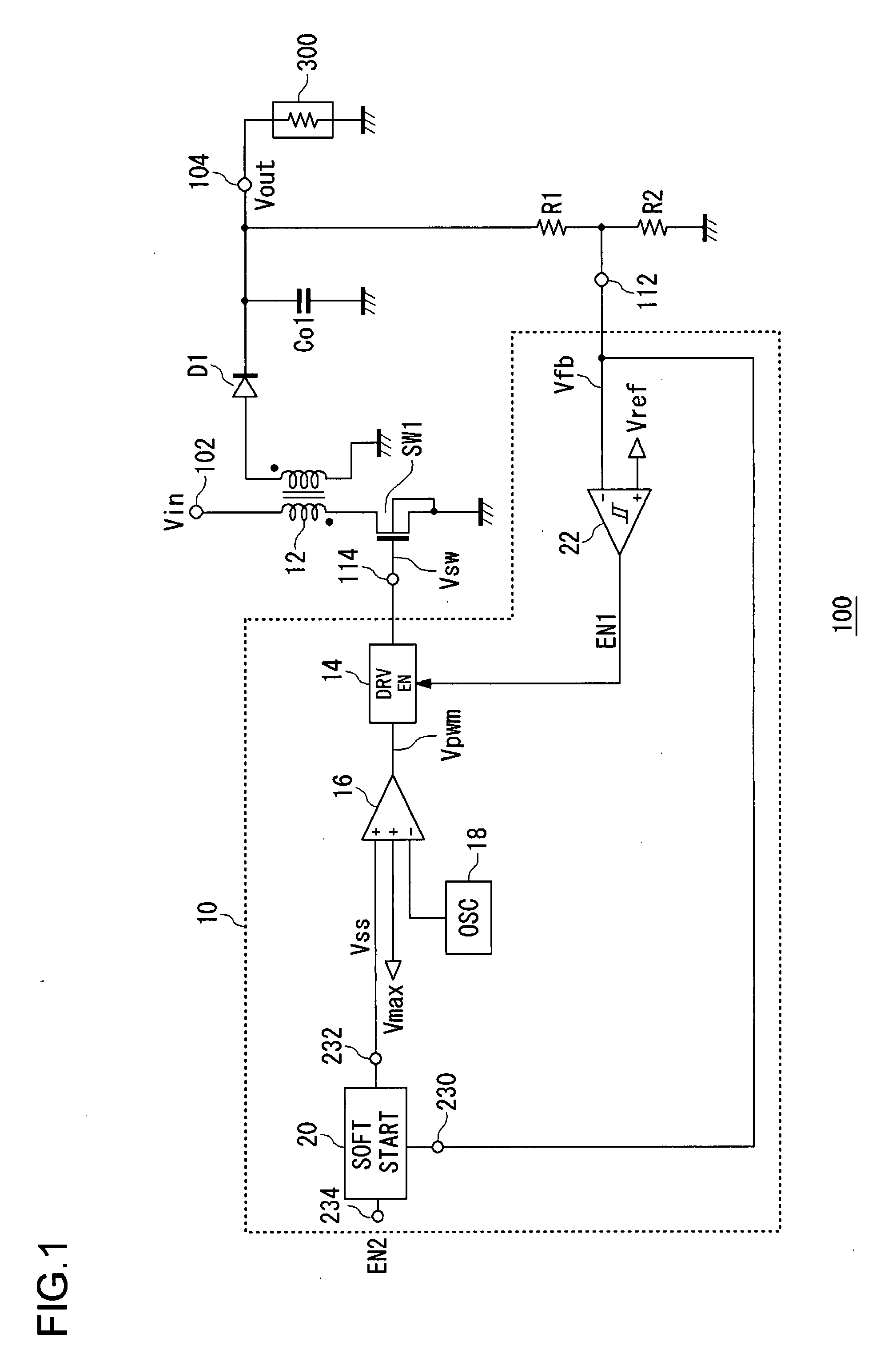
[0032]FIG. 1 is a circuit diagram showing a configuration of a switching power supply 100 of an embodiment. The switching power supply 100 is a boosting-type switching power supply for increasing an input voltage Vin supplied to an input terminal 102 and outputting the boosted voltage from an output terminal 104. To the switching power supply, a load circuit 300 requiring an output voltage of about 300V such as a Xenon lamp is connected.

[0033]The switching power supply 100 is a flyback switching regulator and includes a control circuit 10, a switching element SW1, a transformer 12, a rectifier diode D1, and an output capacitor Co1.

[0034]The switching element SW1 is a MOS transistor and a gate volta...


PUM


Abstract

A control circuit for controlling a switching element in a switching power supply by generating a switching signal is disclosed. The control circuit may include a short start circuit that generates a switching signal so that an output voltage of the switching power supply gradually increases for a period until the output voltage reaches a predetermined reference voltage. The soft start circuit may increase the output voltage at a first limiting speed when the output voltage is lower than a predetermined threshold voltage, and may increase the output voltage at a second limiting speed which is set higher than the first limiting speed when the output voltage is higher than the threshold voltage.

Description

BACKGROUND OF THE INVENTION[0001]1. Field of the Invention[0002]The present invention relates to a switching power supply and, more particularly, to a soft start technique for gradually increasing output voltage of the switching power supply.[0003]2. Description of the Related Art[0004]A boosting-type switching power supply for generating a voltage higher than an input voltage is widely used in various electronic devices. The boosting-type switching power supply has a switching element and an inductor or a transformer. By turning on / off the switching element in discrete time, back electromotive force is generated in the inductor or the transformer to increase the input voltage, and the increased input voltage is output.[0005]In such a switching power supply, to eliminate high frequency components in the boosted voltage and thereby smoothing the boosted voltage, an output capacitor is provided. At the time of starting the switching power supply, the output voltage has to be increased...

Claims


Application Information

Patent Timeline
Patent Type & Authority Applications(United States)
IPC IPC(8): H05B41/36G05F1/10G05F1/00
CPCH02M3/33507H02M1/36H02M3/28H02M1/16
Inventor ARAKI, KYOICHIROTAMEGAI, YOICHIYAMAMOTO, ISAO
Owner ROHM CO LTD
Why Eureka
Try Eureka