DC-DC converter

a converter and dc-dc technology, applied in the direction of dc-dc conversion, power conversion systems, climate sustainability, etc., can solve the problems of intermittent operation and complicated circuit configuration, and achieve the effect of wide load range, reduced output ripple voltage, and high accuracy

Inactive Publication Date: 2006-10-05
PANASONIC CORP
View PDF21 Cites 44 Cited by
  • Summary
  • Abstract
  • Description
  • Claims
  • Application Information

AI Technical Summary

Benefits of technology

[0040] As has been described, in a DC-DC converter according to the present invention, an ON time of a switch can be set to be shorter as a load is lighter. Thus, a continuous operation of an inductor current can be performed with a wider load range. Even if an intermittent operation is started, an output ripple voltage can be reduced. Therefore, an output voltage can be controlled with high accuracy.
[0041] According to the present invention, a valley value of an inductor current is controlled for output control. Specifically, in a current mode control DC-DC converter for controlling an OFF time of a high side switch, with a lighter

Problems solved by technology

Therefore, to precisely detect a current for a power supply voltage which is likely to fluctuat

Method used


Image

  • DC-DC converter
  • DC-DC converter
  • DC-DC converter

Examples


first embodiment

[0052] Hereinafter, a DC-DC converter according to a first embodiment of the present invention will be described with reference to FIGS. 1 through 5.

[0053] First, a circuit configuration of the DC-DC converter of the first embodiment of the present invention will be described.

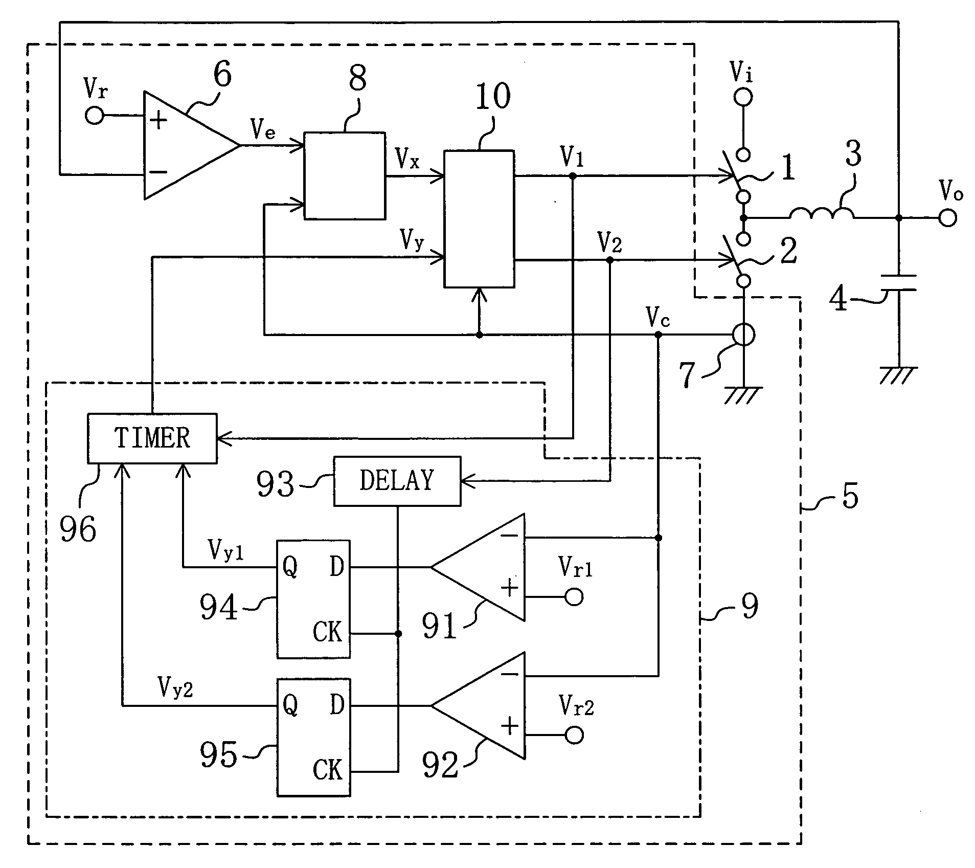
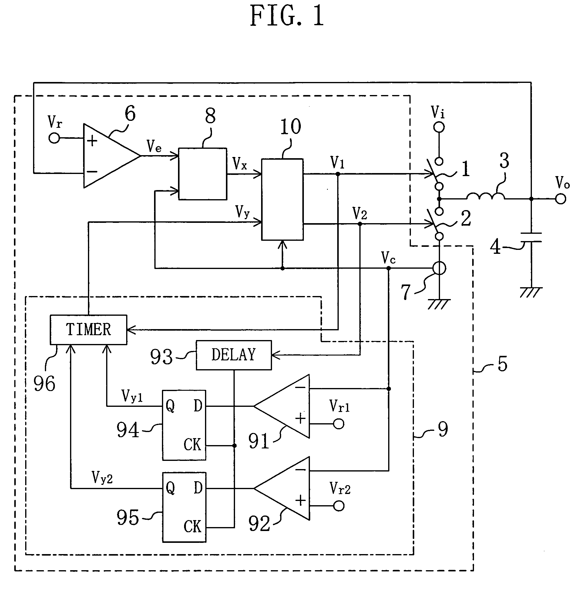
[0054]FIG. 1 is a block diagram illustrating an exemplary circuit configuration of the DC-DC converter of the first embodiment of the present invention.

[0055] As shown in FIG. 1, the DC-DC converter of the first embodiment of the present invention includes a high side switch 1, a low side switch (rectifier) 2, an inductor 3, an output capacitor (smoothing circuit) 4 and a control circuit 5. An input terminal receives an input voltage Vi and an output terminal outputs an output voltage Vo.

[0056] The control circuit 5 includes an output detection circuit 6, a current detection circuit 7, a first circuit 8, a second circuit 9 and a driving circuit 10.

[0057] The second circuit 9 includes a first comparator 91,...

second embodiment

[0099] Hereinafter, a DC-DC converter according to a second embodiment of the present invention will be described with reference to FIG. 6.

[0100] First, a circuit configuration of a DC-DC converter according to the second embodiment of the present invention will be described.

[0101]FIG. 6 is a circuit diagram illustrating an exemplary circuit configuration of the DC-DC converter of the second embodiment of the present invention. In the DC-DC converter of the second embodiment shown in FIG. 6, each member also shown in FIG. 1 of the first embodiment is identified by the same reference numeral and therefore the description thereof will be omitted.

[0102] The DC-DC converter of the second embodiment shown in FIG. 6 is different from the DC-DC converter of the first embodiment shown in FIG. 1 in a configuration of a control circuit. Specifically, the control circuit 5a in the DC-DC converter of the second embodiment includes an output detection circuit 6, a current detection circuit 7,...


PUM


Abstract

A DC-DC converter includes a switch, a rectifier, a smoothing circuit, and a control circuit. The control circuit includes an output detection circuit for outputting an error signal, a current detection circuit for outputting a current detection signal in a period in which at least the switch is OFF, a first circuit for outputting a first signal for setting a timing of turning ON of the switch according to a comparison result between the error signal and the current detection signal, and a second circuit for outputting a second signal for setting an ON time of the switch, according to a reduction in output power from the smoothing circuit, so that the ON time of the switch is reduced, and generates the control signal, based on the first and second signals.

Description

CROSS REFERENCE TO RELATED APPLICATIONS [0001] The disclosure of Japanese Patent Application No. 2005-107826 filed on Apr. 4, 2005 including specification, drawings and claims are incorporated herein by reference in its entirety. BACKGROUND OF THE INVENTION [0002] The present invention relates to a DC-DC converter for supplying a controlled DC (direct current) voltage to various kinds of electronic equipment, and more particularly relates to a control system for adjusting an OFF time of a switch which is a major component of a DC-DC converter. [0003] In recent years, a DC-DC converter is used for a CPU power supply for personal computer and the like in many cases. For example, a step-down DC-DC converter for controlling a lower DC voltage than a power supply voltage and supplying the controlled DC voltage to a load includes an inductor, a high side switch and a low side switch. The high side switch and the low side switch are connected in series between a power supply voltage and a ...

Claims


Application Information

Patent Timeline
IPC IPC(8): G05F1/00
CPCH02M3/157Y02B70/1466H02M3/1588Y02B70/10
Inventor SAITO, HIROSHIWATABE, RYOUISHII, TAKUYA
Owner PANASONIC CORP
Why Eureka
Try Eureka