Test rig

a test rig and rotor technology, applied in the field of test rigs, can solve the problems of expensive maintenance and repair procedures, and excessive wear and material fatigue of various structural elements

Inactive Publication Date: 2014-05-01
SIEMENS AG
View PDF15 Cites 6 Cited by
  • Summary
  • Abstract
  • Description
  • Claims
  • Application Information

AI Technical Summary

Benefits of technology

[0007]It is therefore an object of the invention to p...

Problems solved by technology

For example, the forces acting on a wind turbine nacelle and tower during operation of the wind turbine can result in excessive wear and material fatigue of various structural elements such as bearings, nacelle, bedframe hub, yaw ring, etc.
Excessive wear on parts such as bearings can require expensive maintenance and repair procedures, while material fatigue can lead to the development of hairline cracks or larger cracks, ultimately leading to serious damage and component failure.
However, it is difficult to predict the likelihood, the location and the extent of such damage.
For example, material fatigue can take a long time to develop.
Therefore, manufactures of such structures may invest considerable effort in structural testing, and may attempt to model the effects of loading over a relatively short time in order to predict the real effects of loading during the actual lifetime of a structure.
A degree of freedom or a certain amount of elasticity may be unavoidable, since the test rig itself is made of several elements t...

Method used


Image

  • Test rig
  • Test rig
  • Test rig

Examples


Embodiment Construction

[0043]In the diagrams, like numbers refer to like objects throughout. Objects in the diagrams are not necessarily drawn to scale.

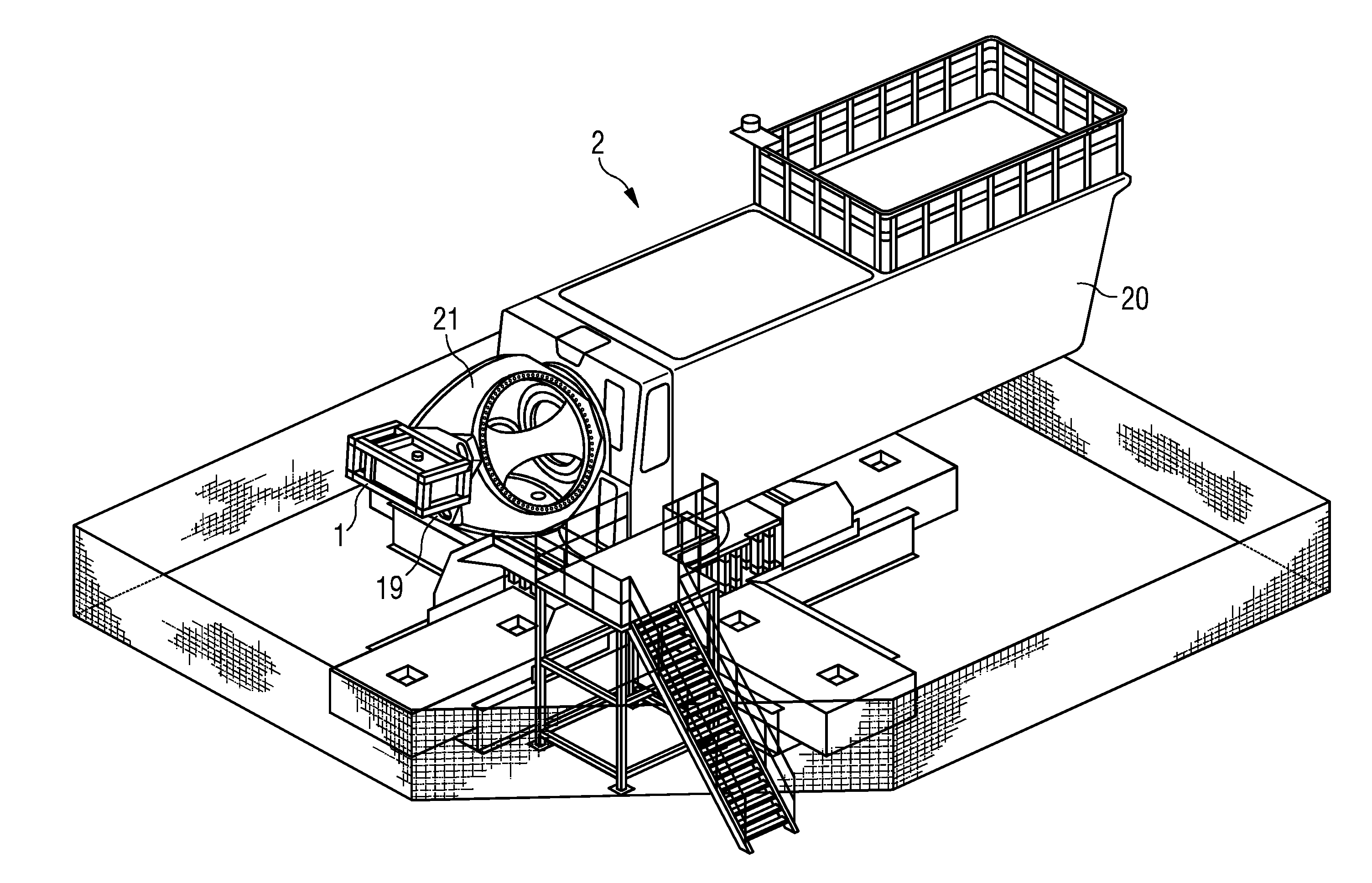
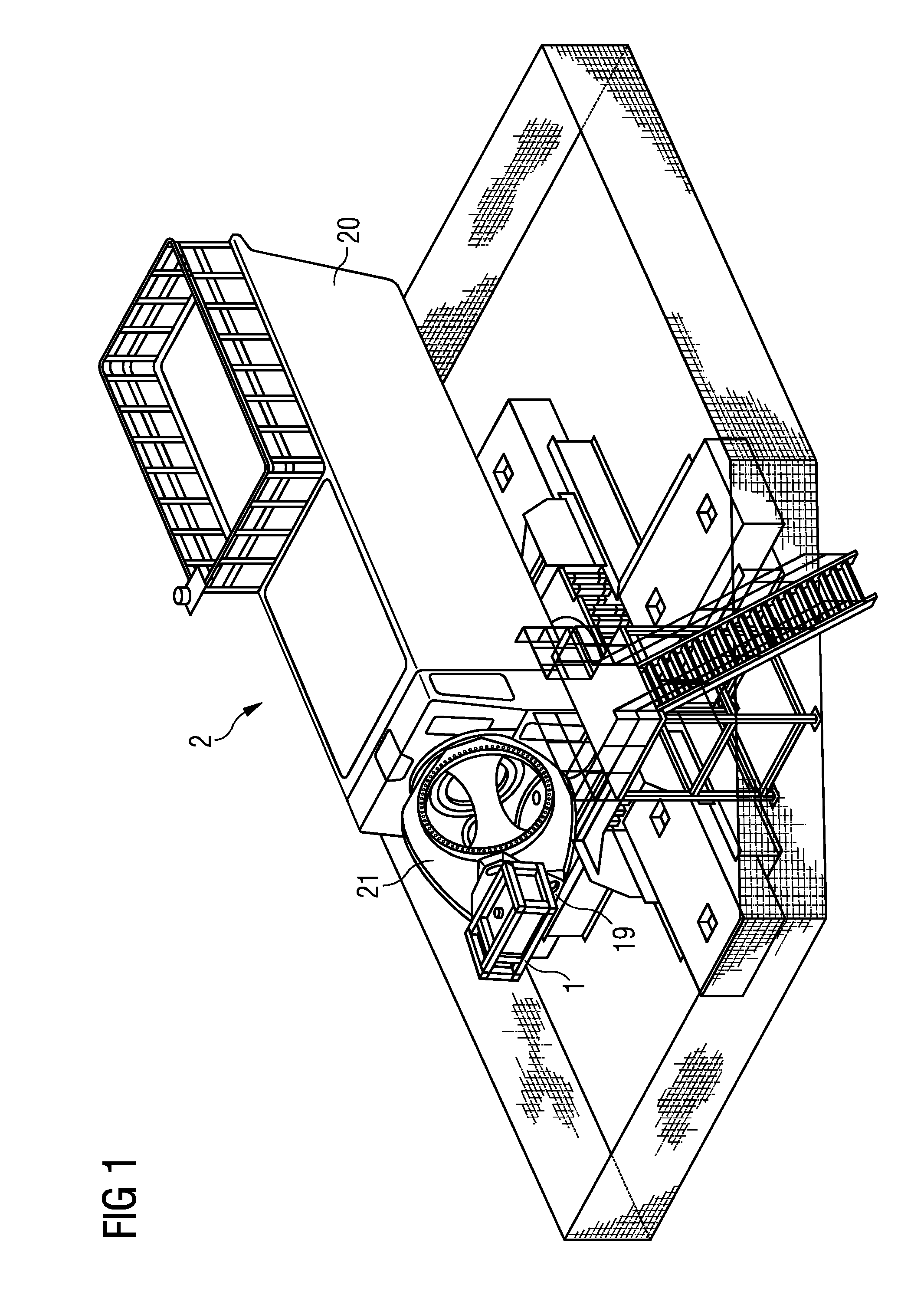
[0044]FIG. 1 shows an embodiment of a wind turbine test setup 2 according to the invention. The component under test comprises a nacelle 20 and hub 21 of a wind turbine. The same type of model can be used as would be used in real-life, and the nacelle 20 can be mounted on a tower model (for example a short-spring arrangement) that imitates the behaviour of an appropriate tower construction. To imitate the effects of the rotor blade rotation and wind loading, a test rig 1 according to the invention is mounted securely to the hub 21 by means of an adapter 19 or connecting means 19 so that centrifugal forces generated in the test rig are transferred essentially undiminished as lateral forces F to the hub 21 and nacelle 20.

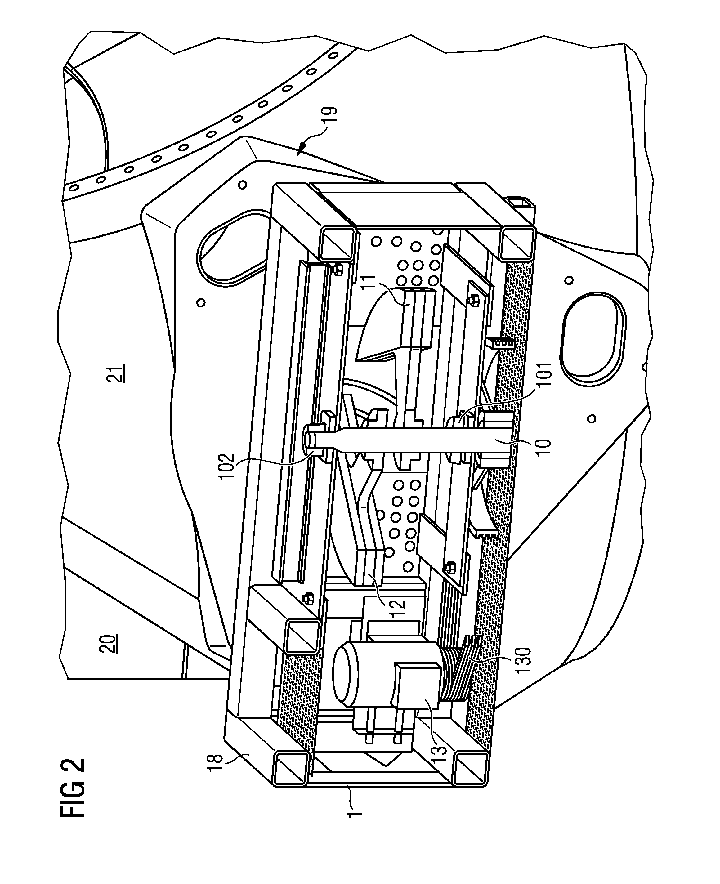
[0045]FIG. 2 shows a partial cut-away of an embodiment of a test rig 1 according to the invention. The test rig 1 comprises a cage 18 or fr...


PUM


Abstract

A test rig for testing a component in a wind turbine is proposed. The test rig has an adjustable radial weight arrangement mounted on a rotatable shaft; a driving means for rotating the shaft at a shaft rotational velocity; and an adjusting means for adjusting the centre of mass of the adjustable radial weight arrangement relative to the shaft while the shaft is rotating. A wind turbine test setup for testing components of a wind turbine has a test rig mounted to a component such that centrifugal forces generated by the rotating radial weights during operation of the test rig are transferred as lateral forces to the wind turbine component under test.

Description

CROSS REFERENCE TO RELATED APPLICATIONS[0001]The present application claims priority to European Patent Office application No. 12190856.0 EP filed Oct. 31, 2012, the entire content of which is hereby incorporated herein by reference.FIELD OF INVENTION[0002]The invention describes a test rig for testing a component, a wind turbine test rig, and a method of testing a component.BACKGROUND OF INVENTION[0003]Certain structures such as tall towers, wind turbines, etc. are subject to structural loading during their lifetime. For example, the forces acting on a wind turbine nacelle and tower during operation of the wind turbine can result in excessive wear and material fatigue of various structural elements such as bearings, nacelle, bedframe hub, yaw ring, etc. Excessive wear on parts such as bearings can require expensive maintenance and repair procedures, while material fatigue can lead to the development of hairline cracks or larger cracks, ultimately leading to serious damage and compo...

Claims


Application Information

Patent Timeline
IPC IPC(8): F03D11/00
CPCY02E10/726G01M7/00F03D11/0091G01M13/025G01M13/027G01M7/045F03D17/00Y02E10/72
Inventor JENSEN, BRIAN GABE
Owner SIEMENS AG
Why Eureka
Try Eureka