System for optically detecting position of an indwelling catheter

a catheter and optical detection technology, applied in the field of quick, non-invasive, radiation-free devices, can solve the problems of limiting the ultimate effectiveness of x-ray radiation, affecting the patient's overall health, and requiring access inside the catheter

Inactive Publication Date: 2011-07-07
ARTANN LAB
View PDF23 Cites 43 Cited by
  • Summary
  • Abstract
  • Description
  • Claims
  • Application Information

AI Technical Summary

Benefits of technology

[0013]It is a further object of the present invention to provide an optical cathe

Problems solved by technology

However, excessive exposure to X-ray radiation by both the patient and clinician can be harmful.
This method requires some subjectivity which limits its ultimate effectiveness.
An important limitation of this device is the need to gain access inside the catheter for its proper function.
A general limitation of magnetic tracking systems is a risk

Method used


Image

  • System for optically detecting position of an indwelling catheter
  • System for optically detecting position of an indwelling catheter
  • System for optically detecting position of an indwelling catheter

Examples


first embodiment

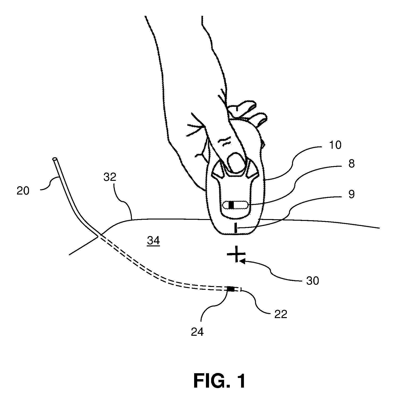
[0030]FIG. 2 is a schematic view of the present invention in which a probe 10 includes a light emitter 12 and a pair of light detectors 16 and 18 positioned on both sides of the emitter 12 along a first axis aligned with the projected travel path of the catheter, preferably at an equal distance therefrom. The probe 10 is shown positioned over the optical marker 24 at the tip of a catheter 20. The light emitter 12 may be a light-emitting diode (LED) while the light detectors 16 and 18 may be photodiodes. Preferably, a high-speed high-power infra-red LED is used as a light emitter 12 while an integrated photodiode and amplifier is used as a light detector 16 and 18. To ensure the highest tissue penetration and the least absorption when passing through tissue, the range of wavelengths for the light emitter 12 is preferably selected to be from about 650 nm to about 900 nm. Shorter wavelengths may cause increased absorption by hemoglobin in blood while longer wavelengths may be absorbed ...

second embodiment

[0034]FIG. 4 is a schematic view of the optical probe 10 with a light emitter 12 and a linear array of light detectors including a first array of at least two light detectors 16 and 16′ on one side of the light emitter 12 and a second array of at least two light detectors 18 and 18′ on the other side of light emitter 12. The light emitter 12 and the light detectors 16, 16′, 18, and 18′ are placed along a probe axis formed as a straight line and oriented along a projected travel path of the catheter tip with the embedded optical marker 24.

[0035]There are several advantageous ways to utilize detector arrays of this embodiment. In one way, all detectors are turned on at all times during the catheter position identification process. Having more than one detector allows further reduction in noise and increase in accuracy of position detection. Alternatively, these detectors can be turned on and off at various stages of catheter detection procedure. At first, outside detectors can be turn...

third embodiment

[0036]FIG. 5 is a schematic view of the invention in which the probe includes a light emitter 12 and two transversely oriented pairs of the light detectors 16 and 16′ along a first axis as well as 18 and 18′ along a second axis. The first pair of detectors 16 and 16′ is preferably oriented along the projected travel path of the catheter tip with the optical marker 24, while the second pair of light detectors 18 and 18′ are placed on an axis orientated in the perpendicular direction. Detection of both magnitude and direction of travel of the optical marker 24 is carried out in the axial and lateral directions by comparing the current optical signals with the reference signals.

[0037]FIG. 6 shows the principle behind the detection of a two dimensional displacement of the catheter tip as the combination of two vectors corresponding to the axial and lateral displacements which are measured by transversally oriented pairs of light detectors with a light emitter 12 positioned in the center...


PUM


Abstract

The present invention relates generally a device for locating an indwelling catheter relative to its initial location. The system of the invention is based on emitting light from an optical probe placed on the patient to an optical marker on the tip of the catheter. The reflected light from the optical marker is then detected by the optical probe and the reading is recorded to memory as the reference measurement. The position of the optical probe on the patient is marked so that future measurements are taken from the same location. These future measurements will be compared to the reference measurement and from this comparison the displacement of the tip of the catheter is found and can be corrected. This system is fast, non-invasive, radiation free, and accurate to within 2-3 mm.

Description

BACKGROUND OF THE INVENTION[0001]The present invention relates to a quick, non-invasive, radiation-free device to determine a position of indwelling catheters within the human or animal body. The term catheter as used throughout this description refers to any type of invasive surgical tool, used for insertion into a human or animal body for the purpose of providing remote access to a part of the body for performing some type of investigative and / or therapeutic medical procedure. Examples of such tools include various catheters, tubes, endotracheal tubes, cannulaes, probes etc.[0002]With the increasing use of minimally invasive surgical techniques in medical diagnosis and therapy, there is a need for new methods of remotely locating and tracking catheters or other medical instruments inside a human or animal body. Currently, X-ray imaging is the standard catheter tracking technique. However, excessive exposure to X-ray radiation by both the patient and clinician can be harmful. Thus,...

Claims


Application Information

Patent Timeline
IPC IPC(8): A61B6/00
CPCA61B5/06A61B19/5244A61B2019/5272A61B2019/5255A61B2019/5251A61B2034/2055A61B2034/2072A61B34/20A61B2034/2051A61B5/064
Inventor SARVAZYAN, ARMEN P.
Owner ARTANN LAB
Why Eureka
Try Eureka