
Eureka
For R&D, Eureka makes reading and utilizing patents & technical documents easy.
Eureka AIR
Designed for self-driven R&D workflows. Generate viable solutions, solve complex R&D challenges, empower your innovation with AI.

Eureka Materials
Designed for material experts only. Revolutionize your material R&D, from search, analyze, to developing new materials.

TechResearch
Generate reliable direction feasibility study reports for your R&D in just a few steps.

TechSeek
Discover and master advanced knowledge NOW. Basics, ideas, possibilities, all at once.

TechMind
As an expert in R&D Theories, TechMind can generates customized viable solutions instantly.

TechRisk
Analyze your overall solution with one click, know your potential R&D risks in advance.

TechMonitor
Get weekly tech updates, stay abreast of the latest tech innovations and key insights.
Slide Door Apparatus for Vehicle
- Summary
- Abstract
- Description
- Claims
- Application Information
AI Technical Summary
Problems solved by technology
Method used
Image

Examples
first embodiment
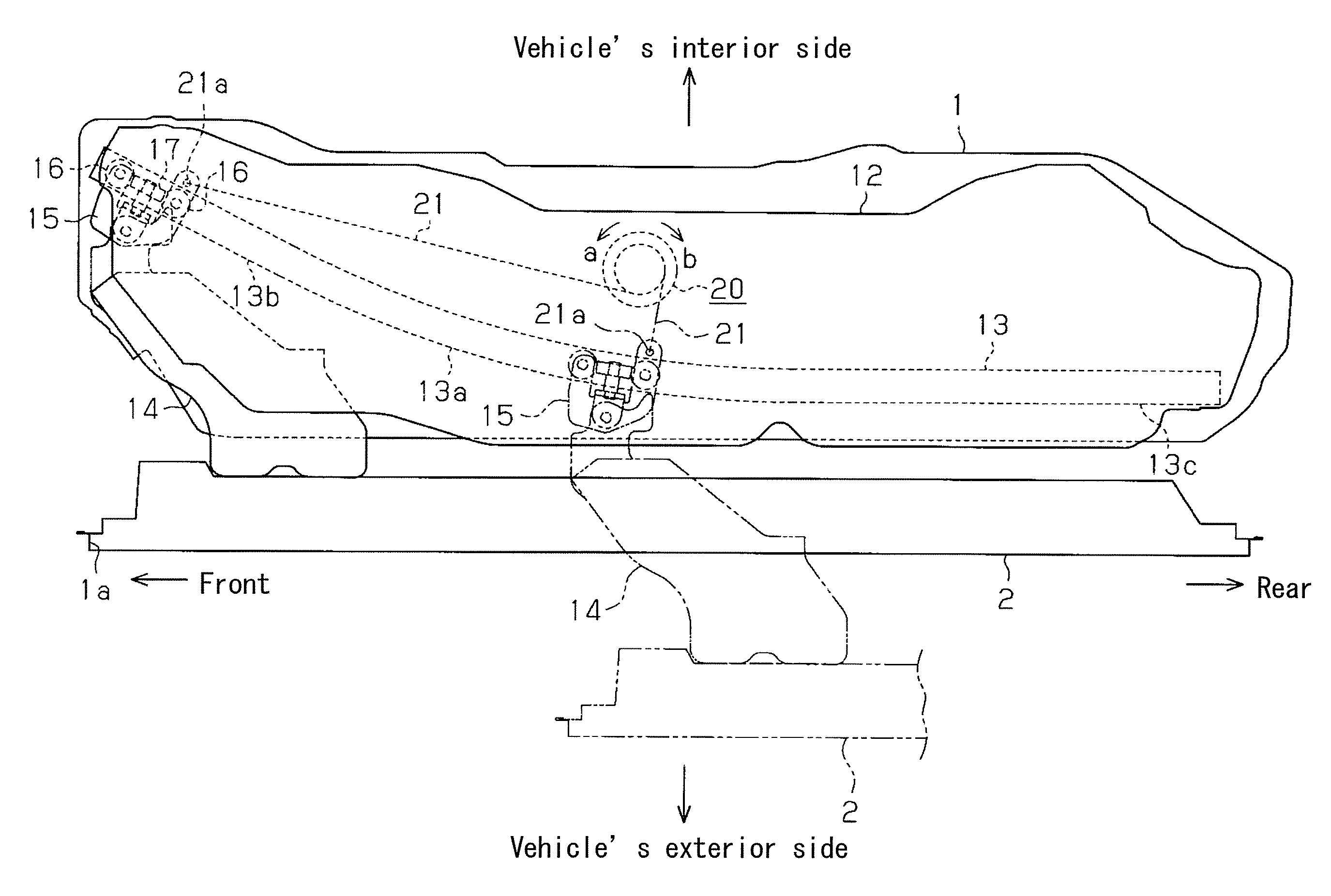
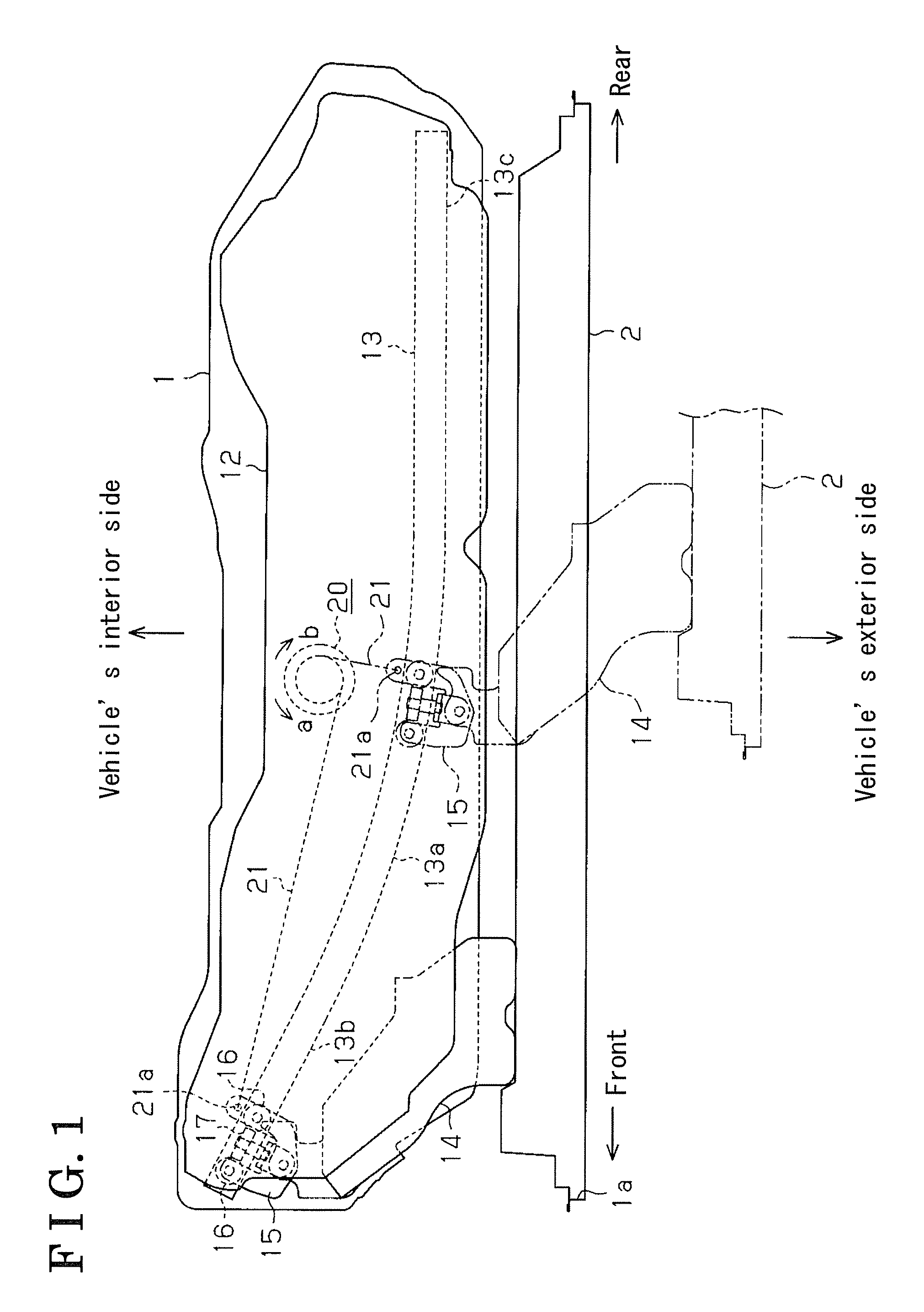
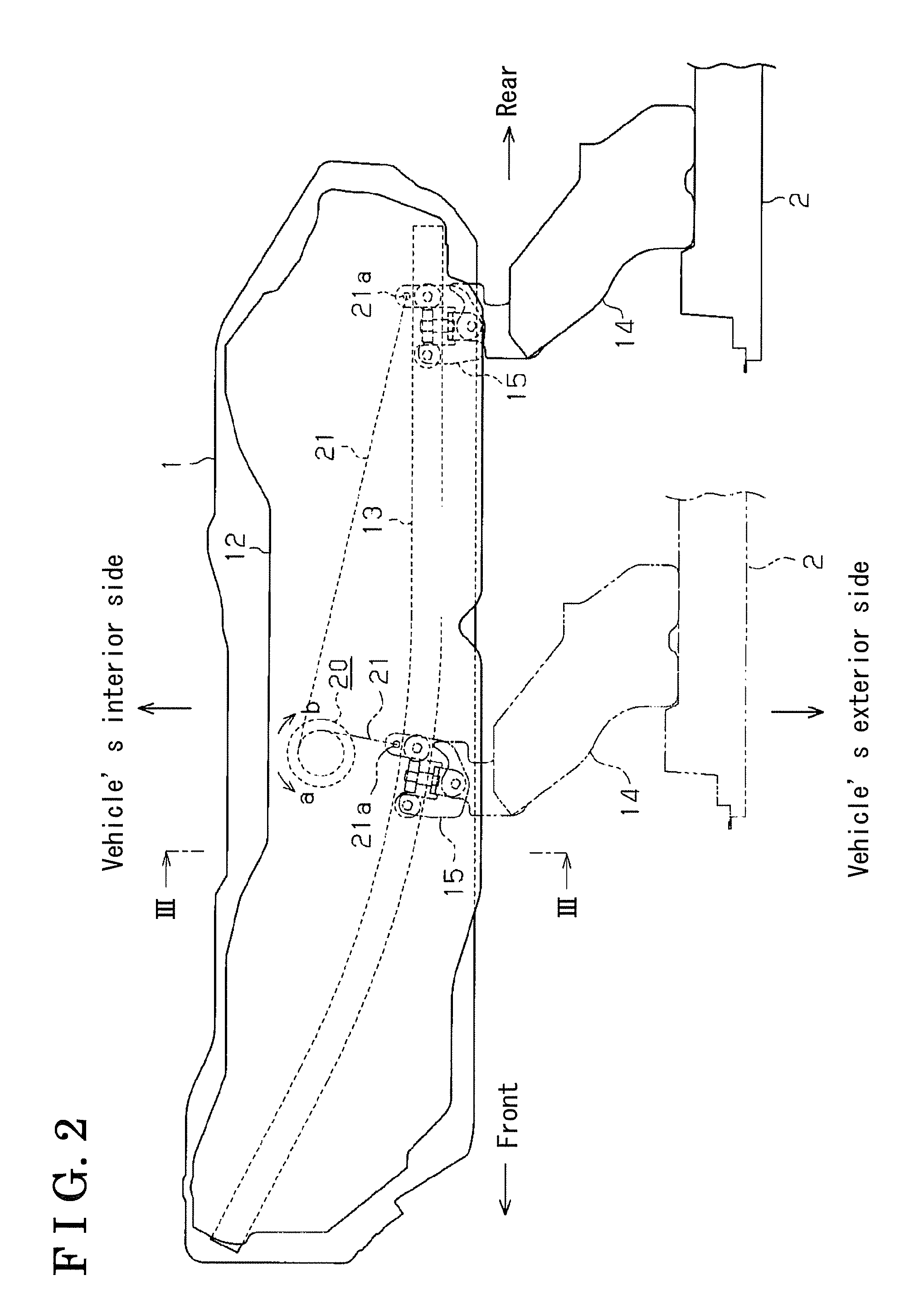
[0050]Here, an operation of the slide door 2 will be explained as a whole below. As illustrated in FIGS. 1 and 2, when the slide door 2 moves from the predetermined partly opened position to the fully closed position or the fully opened position in accordance with opening and closing operations of the slide door 2, the rope member 21 is unreeled from the reel member 31 along with the opening and closing operations. Further, the reel member 31 rotates in the direction where the reel member 31 unreels the rope member 21, thereby rotating the internal rotor 44 integrally with the reel member 31 in the direction “b.” In this case, when a rotating speed of the internal rotor 44 is low and a speed of the internal rotor 44 is within the range of the normal opening and closing speeds of the slide door 2, a rotating load (braking) generated by the rotating device 41 undergoes the approximately small constant value. Accordingly, the slide door 2 is operated to open and close at a relevant sm...
second embodiment
[0063]As illustrated in FIG. 11, the speed control mechanism 20 is mounted on an upper surface of the arm 14. The first terminal end 21a of the rope member 21 is rotatably connected to the support panel 12 so as to be located more outwardly than the guide rail 13 at the intermediate part in the longitudinal direction of the vehicle. The rope member 21 extends linearly toward the support panel 12 to which the first terminal end 21a is connected. When the slide door 2 moves from the predetermined partly opened position to the fully closed position or the fully opened position, the rope member 21 is unreeled from within the speed control mechanism 20 (a reel member 104). Meanwhile, when the slide door 2 moves from the fully closed position or the fully opened position to the predetermined partly opened position, the rope member 21 is reeled within the speed control mechanism 20 (reel member 104) by the biasing force of the spring 32 (see FIG. 12).
[0064]Here, the speed control mechanis...
fourth embodiment
[0081]A rope member 87 is wound around an outer peripheral surface of the reel portion 86a. A first terminal end (21a) of the rope member 87 is rotatably connected to the slide door 2 (arm 14) or the vehicle body 1 (support panel 12). A second terminal end (21b) of the rope member 87 is locked on the outer peripheral surface of the reel portion 86a. The rope member 87 has its own spring force, thereby generating a biasing force acting when the reel member 86 rotates in the direction “a” where the reel member 86 reels the rope member 87. Accordingly, a biasing member (the spring 32) is not disposed in an inner circumferential space of the reel portion 86a.
[0082]An internal rotor 88 accommodated in an internal space formed by the cover 84 (cylindrical tube 84b) and the cover 85 includes a shaft portion 88b having a square-shaped mating hole 88a mating with the mating shaft portion 86c. The shaft portion 88b is rotatably supported in the bearing holes 84a and 85a for liquid tight sea...
PUM
 Abstract
Description
Claims
Application Information
 - R&D Engineer
- R&D Manager
- IP Professional
- Industry Leading Data Capabilities
- Powerful AI technology
- Patent DNA Extraction
Browse by: Latest US Patents, China's latest patents, Technical Efficacy Thesaurus, Application Domain, Technology Topic, Popular Technical Reports.
© 2024 PatSnap. All rights reserved.Legal|Privacy policy|Modern Slavery Act Transparency Statement|Sitemap|About US| Contact US: help@patsnap.com