Automated diagnostics for crawler transmission hydraulic circuits

a hydraulic circuit and crawler technology, applied in the field of automatic diagnostic system, can solve the problems of significant increase in warranty cost, tedious and ambiguous task of diagnosing hydrostatic transmission problems,

Active Publication Date: 2009-02-12
DEERE & CO
View PDF12 Cites 10 Cited by
  • Summary
  • Abstract
  • Description
  • Claims
  • Application Information

AI Technical Summary

Benefits of technology

[0005]It is another object of the present invention to drive appropriate electrical signals to control the transmission hydraulic components while the microprocessor reads resulting speeds and pressures. A further object of the invention is that the microprocessor can perform calculations on the results, determine the hydraulic problem, and provide feedback to the technician on adjustments for part replacements that need to be made.

Problems solved by technology

Diagnosing problems in a hydrostatic transmission can be a tedious and ambiguous task.
Another problem with current testing techniques is that, as the technician may be uncertain as to the real cause of a problem, a parts-swapping approach may be taken to pick and choose parts to replace until the appropriate nonfunctioning part is removed.
This type of approach can significantly increase warranty costs as non-defective parts may be replaced.

Method used


Image

  • Automated diagnostics for crawler transmission hydraulic circuits
  • Automated diagnostics for crawler transmission hydraulic circuits
  • Automated diagnostics for crawler transmission hydraulic circuits

Examples


Embodiment Construction

[0033]For the purposes of promoting an understanding of the principles of the invention, reference will now be made to the embodiments illustrated in the drawings, which are described below. It will nevertheless be understood that no limitation of the scope of the invention is thereby intended. The invention includes any alterations and further modifications in the illustrated devices and described methods and further applications of the principles of the invention, which would normally occur to one skilled in the art to which the invention relates.

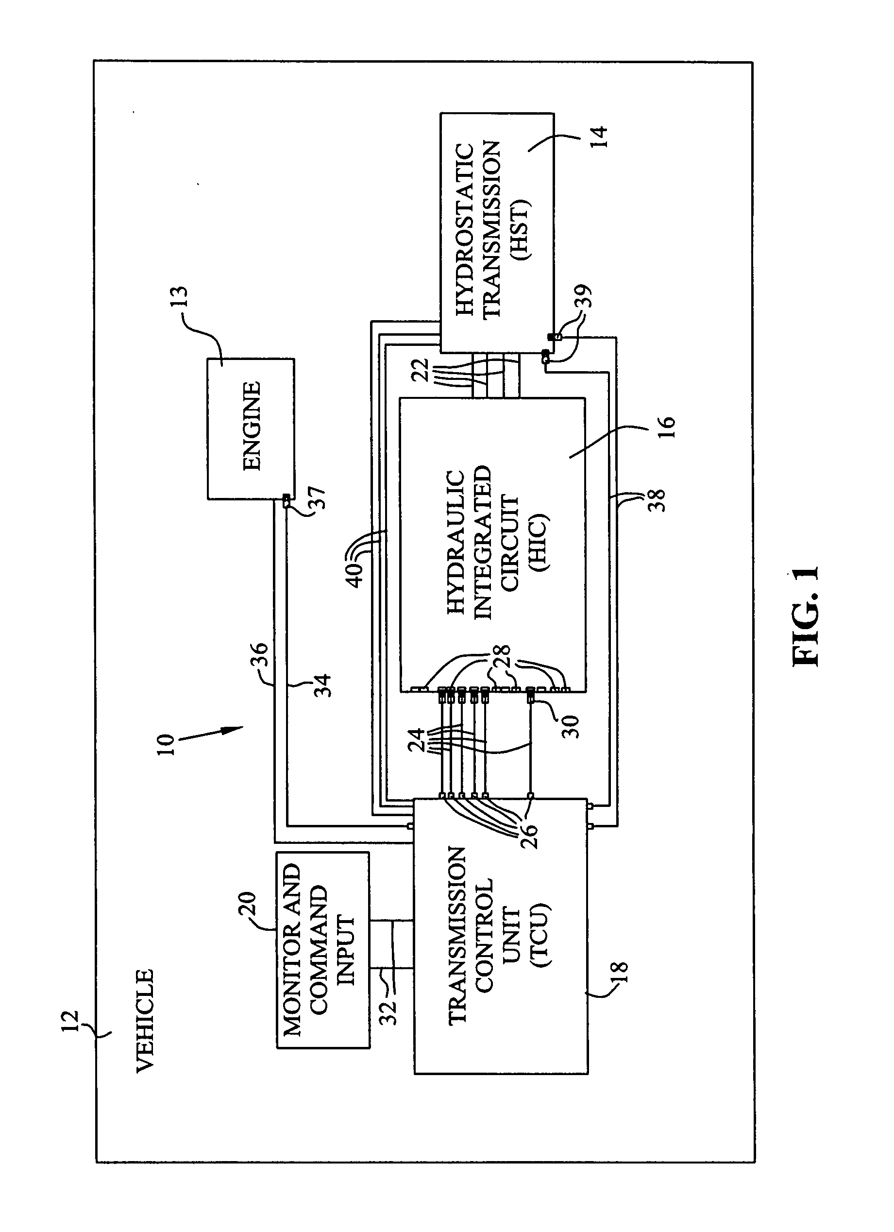
[0034]Now referring to FIG. 1, one embodiment of a diagnostic system for diagnosing problems in a hydrostatic transmission is shown, generally indicated as 10. Diagnostic system 10 is mounted on a vehicle 12. Vehicle 12 includes an engine 13, a hydrostatic transmission 14, a hydraulic integrated circuit 16, a transmission control unit 18, and a monitor with command input 20. In addition, vehicle 12 includes hydraulic couplings 22 between ...


PUM


Abstract

A diagnostic system and method for diagnosing problems in a hydrostatic transmission of a vehicle including a transmission control unit that has a monitor and pressure sensors and at least one temperature sensor connectable between diagnostic hose ports coupled to the transmission and inputs on the transmission control unit. A symptom or problem area is selected on the monitor; and a test sequence is initiated by command input on the monitor. The transmission control unit performs calculations based upon input data from the pressure sensors to determine a hydraulic problem, and provides directions for adjustments or replacing parts on the hydrostatic transmission. The monitor may provide instructions to relocate existing sensor connections for the test sequence selected.

Description

BACKGROUND OF THE INVENTION[0001]This invention relates to diagnostic testing of a hydrostatic transmission, and in particular, to an automated diagnostic system that can run tests that would normally be conducted manually by a technician.[0002]Diagnosing problems in a hydrostatic transmission can be a tedious and ambiguous task. In order to ascertain if particular components are functioning properly, a technician typically installs a variety of pressure or flow gauges, taps into the electrical circuits, and then follows testing procedures. The testing procedures include making notes and performing calculations to try to ascertain that the individual components are functioning properly. Such tests can also be subjective and highly dependent upon the skills and dedication of the technician to following procedures.[0003]Another problem with current testing techniques is that, as the technician may be uncertain as to the real cause of a problem, a parts-swapping approach may be taken t...

Claims


Application Information

Patent Timeline
Patent Type & Authority Applications(United States)
IPC IPC(8): G01M17/03G06F19/00G06G5/00
CPCG01M13/02G01M3/2846
Inventor ZOPF, WILLIAM DAMM
Owner DEERE & CO
Why Eureka
Try Eureka