[0005]In relation to this prior art, the object of the present intention is to produce a suitable hydraulic
control system in which the hydraulic pulsations behavior is improved.
[0006]According to the invention, a hydraulic
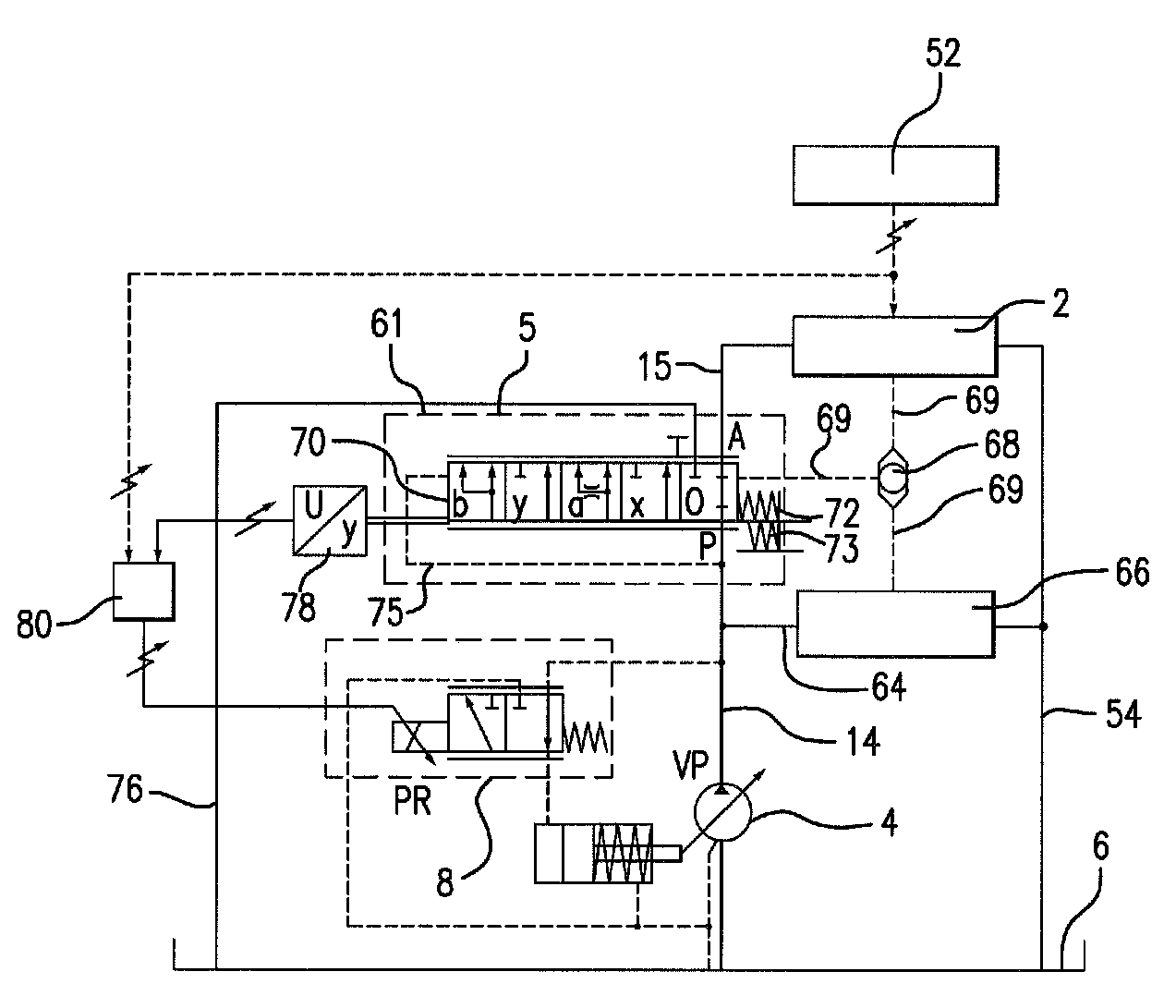
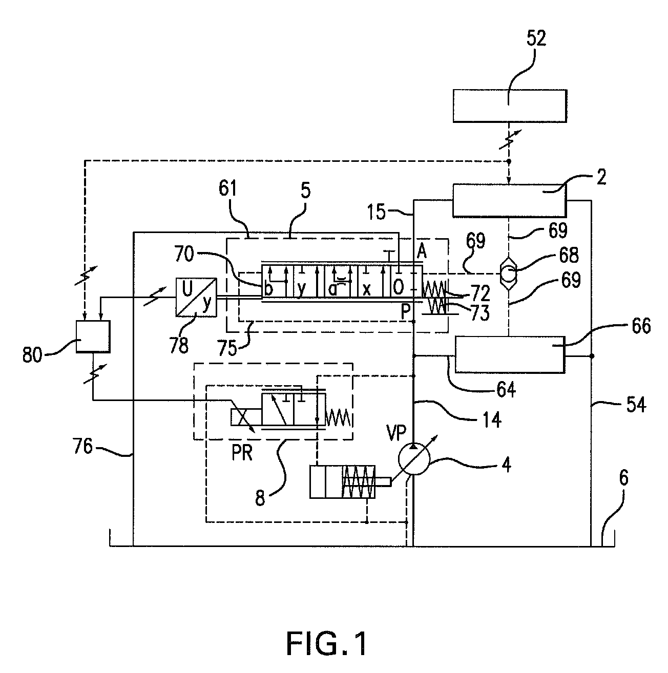
control system preferably controls at least two consumers, e.g. mobile machines, that can be supplied with pressure fluid by a pump with an adjustable delivery quantity and that are each associated with an adjustable metering orifice. The hydraulic control system also has a power beyond connection to which at least one power beyond consumer can be connected and one inlet pressure governor unit (IPGU) downstream of the pump, which is acted on in the closing direction by a load pressure of the consumers or of at least one power beyond consumer. The IPGU is provided in the pressure fluid flow path between the pump and at least one of the two consumers. The power beyond connection branches off from the pressure fluid flow path between the pump and the IPGU; in a spring-prestressed position, this IPGU closes the connection to the at least one of the two consumers and a tank and in another position, it opens a pressure fluid connection to a tank; the IPGU has an additional position in which a throttled connection to the tank is opened. This has the
advantage that in a throttled position of the IPGU, some residual flow of pressure fluid continuously flows out into the tank; this residual flow of pressure fluid does in fact cause minimal pressure fluid losses, but leads to a significantly better system damping of the hydraulic control system.
[0007]In a preferred embodiment, The IPGU is a continuously adjustable 3 / 5-way directional control valve that has a pump connection, a working connection, and a tank connection and can be moved into a closed position, two working positions, and two transition positions; in the two working positions, a communication is opened between the pump connection, the working connection, and the tank connection and in the two transition positions, a communication is opened between the pump connection and the working connection. The single-valve embodiment of the IPGU makes it very compact and space-saving.
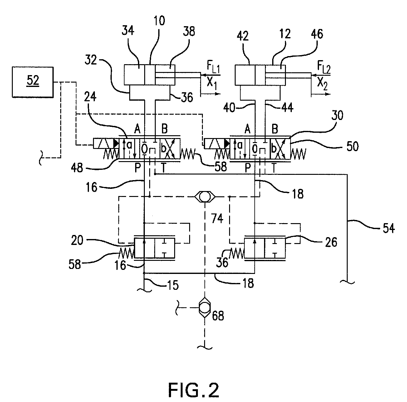
[0008]In another preferred embodiment, the IPGU has at least two continuously adjustable valves; one valve is a 3 / 3-way directional control valve equipped with a pump connection, a working connection, and a tank connection, and the other is a 2 / 3-way tank valve equipped with a pressure connection and a tank connection, whose pressure connection is connected to the working connection of the 3 / 3-way directional control valve. The 3 / 3-way directional control valve can be moved into a closed position and toward two working positions; in one working position, a communication is opened between the pump connection, the working connection, and the tank connection and in the other, a communication is opened between the pump connection and the working connection. The 2 / 3-way tank valve can be moved into a closed position and toward two working positions; in the one working position, a throttled connection is opened between the pressure connection and the tank connection and in the other position, this connection is closed. This dual-valve embodiment is very advantageous since the total length of the IPGU can be significantly reduced.
[0010]In another advantageous embodiment of the IPGU, it has a continuously adjustable 2 / 3-way directional control valve, which is equipped with a pump connection and a working connection, and a continuously adjustable 2 / 3-way tank valve, which is equipped with a pressure connection and a tank connection and whose pressure connection is connected to the working connection. In this case, the one 2 / 3-way directional control valve can be moved into a closed position and toward two working positions; in the working positions, a communication is opened between the pump connection and the working connection. The 2 / 3-way tank valve can also be moved into a closed position and toward two working positions; in the one working position, a throttled connection is produced between the pressure connection and tank connection and in the other, an unthrottled connection is produced between the pressure connection and the tank connection. The low number of inlets and outlets to the valve permits a very simple and therefore very inexpensive embodiment of the valve.

