Submerged fired vertical furnance

a vertical furnance and submerged technology, applied in the field of furnaces, can solve the problems of poor melt quality and relatively high air pollution of solid coke firing, and achieve the effect of efficient utilization

Inactive Publication Date: 2009-02-19
LEWIS ALBERT
View PDF14 Cites 34 Cited by
  • Summary
  • Abstract
  • Description
  • Claims
  • Application Information

AI Technical Summary

Problems solved by technology

Such furnaces have been relatively efficient, but have major shortcomings, including poor quality of the melt, and that the firing of solid coke produces a relatively high degree of air pollution.

Method used


Image

  • Submerged fired vertical furnance
  • Submerged fired vertical furnance

Examples


Embodiment Construction

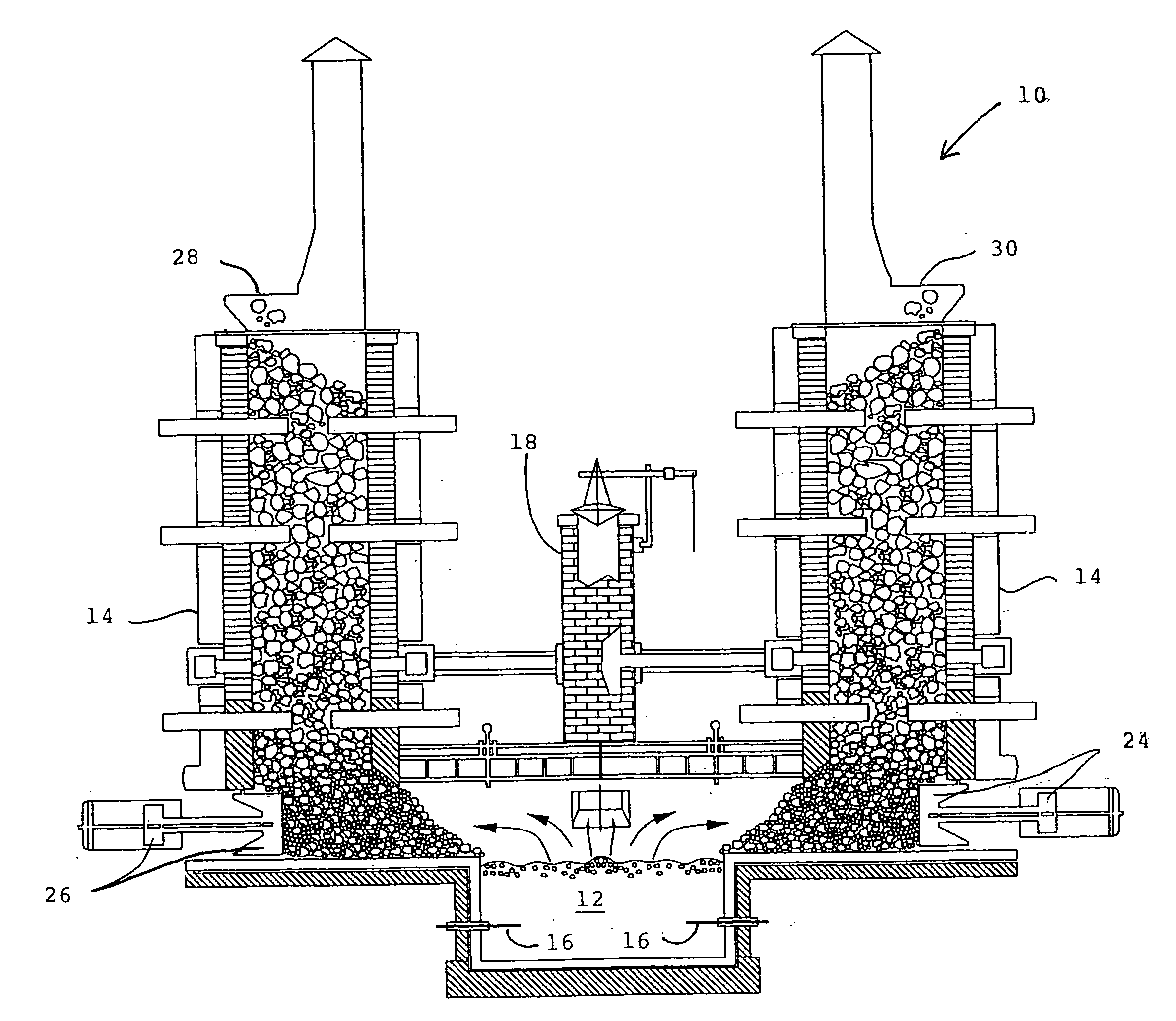
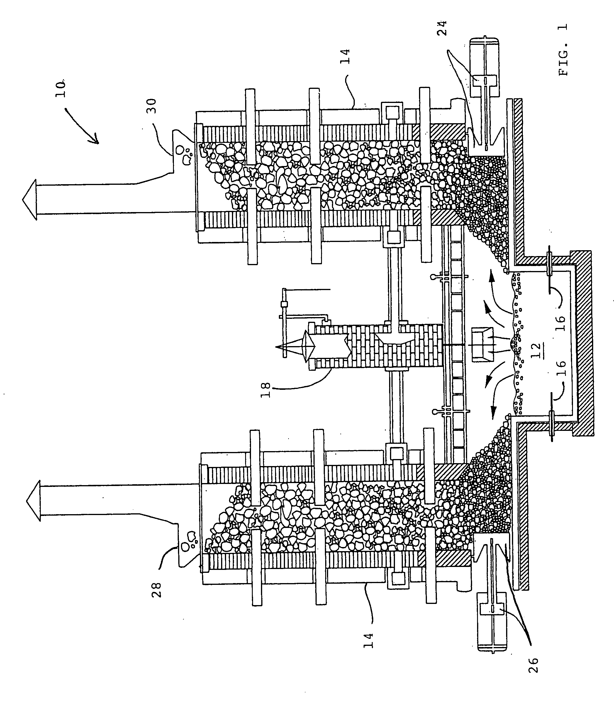
[0015]The present invention relates to a substantially vertical shaft melting furnace wherein solid charge is continuously added and passes downwardly to hot combustion gases in a preheated and sized reduction melting zone, providing intensive preheating and melting of the charge using electricity or heat of combustion gases.

[0016]Prior art conventional melting and heating furnaces are generally reverberatory furnaces and cupolas. Reverberatory furnaces have been very expensive in capital cost and in operation, and have provided low production rates and low thermal efficiency.

[0017]The present invention is a continuous melting furnace which is gas or electrically fired and relates generally to substantially vertical melting furnaces in which charge is continuously added. The burners utilized with the invention may be of any suitable design, and oxidizing gas may preferably be provided.

[0018]A vertical shaft furnace 10 has a melt pool 12 at the bottom thereof and communicating with m...


PUM

PropertyMeasurementUnit
currentsaaaaaaaaaa
viscosityaaaaaaaaaa
heataaaaaaaaaa

Abstract

A furnace is heated by submerged heating equipment. An exhaust stack is vented directly to outside the furnace. A portion of hot gases may pass into at least one shaft via which incoming material and a stage of pre-heating occurs.

Description

CROSS-REFERENCE TO RELATED APPLICATIONS[0001]Not applicable.STATEMENT REGARDING FEDERALLY SPONSORED RESEARCH OR DEVELOPMENT[0002]Not applicable.REFERENCE TO SEQUENCE LISTING, A TABLE, OR A COMPUTER PROGRAM LISTING COMPACT DISC APPENDIX[0003]Not applicable.BACKGROUND AND SUMMARY OF THE INVENTION[0004]The present invention relates to furnaces which are heated by submerged heating equipment which may be gas, oxy / gas or electrically fired.[0005]Water cooled melting furnaces have been used for some years to melt a variety of materials such as metal, rock, glass, etc. Water cooled furnaces for melting glass began in the 1970's. Several types of energy have been utilized, such as electric, gas, and coke.[0006]Conventional cupola furnaces have typically utilized solid coke fuel. Such furnaces have been relatively efficient, but have major shortcomings, including poor quality of the melt, and that the firing of solid coke produces a relatively high degree of air pollution.[0007]The present i...

Claims


Application Information

Patent Timeline
Patent Type & Authority Applications(United States)
IPC IPC(8): C03B5/16
CPCC03B3/00C03B3/02C03B5/027C03B5/2356F27D9/00F27B1/16F27B1/20F27B1/24F27D3/04F27B1/02
Inventor LEWIS, ALBERT
Owner LEWIS ALBERT
Why Eureka
Try Eureka