

Deformable duct guides that accommodate electronic connection lines
- Summary
- Abstract
- Description
- Claims
- Application Information
AI Technical Summary
Benefits of technology
Problems solved by technology
Method used
Image

Examples
first embodiment
[0057]FIG. 4 illustrates an isometric view of an electronics enclosure with an access mechanism in a closed position. An electronics enclosure 110 includes a rear panel 120 including one or more heat exchangers. The one or more heat exchangers are coupled to flexible fluid lines 140 for input and output of cooling fluid. In some embodiments, the electronics enclosure 110 includes a plenum and duct work of the type described above in relation to FIGS. 1-3. In other embodiments, the electronics enclosure 110 may or may not include a plenum and / or duct work between the back of the electronics servers 160 (FIG. 5A) and the rear panel 120.
[0058]FIG. 5A illustrates an isometric view of the electronics enclosure 110 with the access mechanism in an open position. Slide rails 150 are coupled to the rear panel 120 and to the rear end of the electronics enclosure 110. The slide rails 150 enable the rear panel 120 to slide back and forth relative to the electronics enclosure 110, similar to a d...
second embodiment
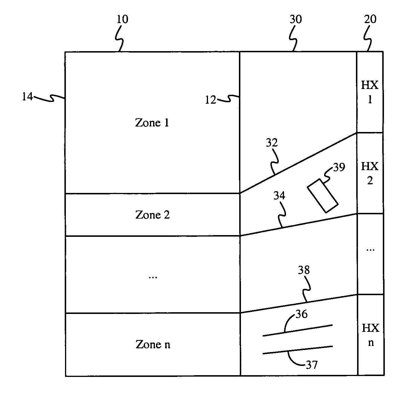
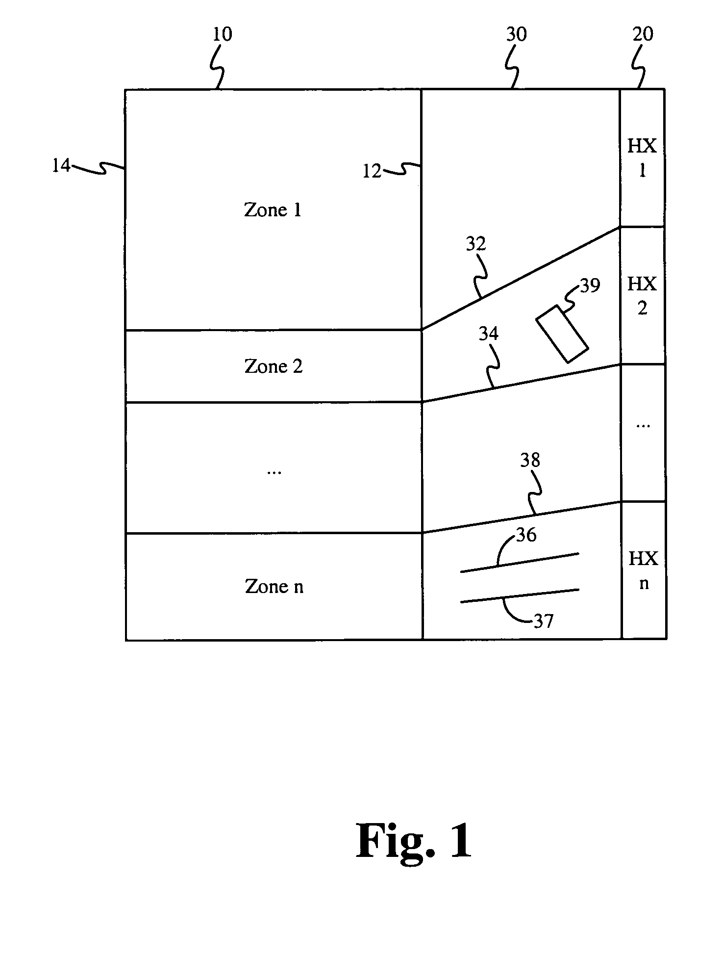
[0062]FIG. 6 illustrates an isometric view of an electronics enclosure with an access mechanism. The rear panel of an electronics enclosure 210 is replaced with a plurality of heat exchangers 222, 224, 226 and duct work 232, 234, 236. The inclusion of three sets of heat exchangers and duct works is for exemplary purposes only, more or less than three sets of heat exchangers and duct works can be used. Each of the heat exchangers 222, 224, 226 is coupled to fluid lines 240 for input and output of cooling fluid. The fluid lines can be flexible or hard-plumbed. Air output from the back of the electronics enclosure 210 is directed to each of the heat exchangers 222, 224, 226 via the duct work 232, 234, 236, respectively. The heat exchangers 222, 224, 226 are each positioned substantially horizontally, and the duct work 232, 234, 236 redirects the substantially horizontal air flow out the back of the electronic enclosure 210 to a substantially upward vertical air flow directed to the hea...
third embodiment
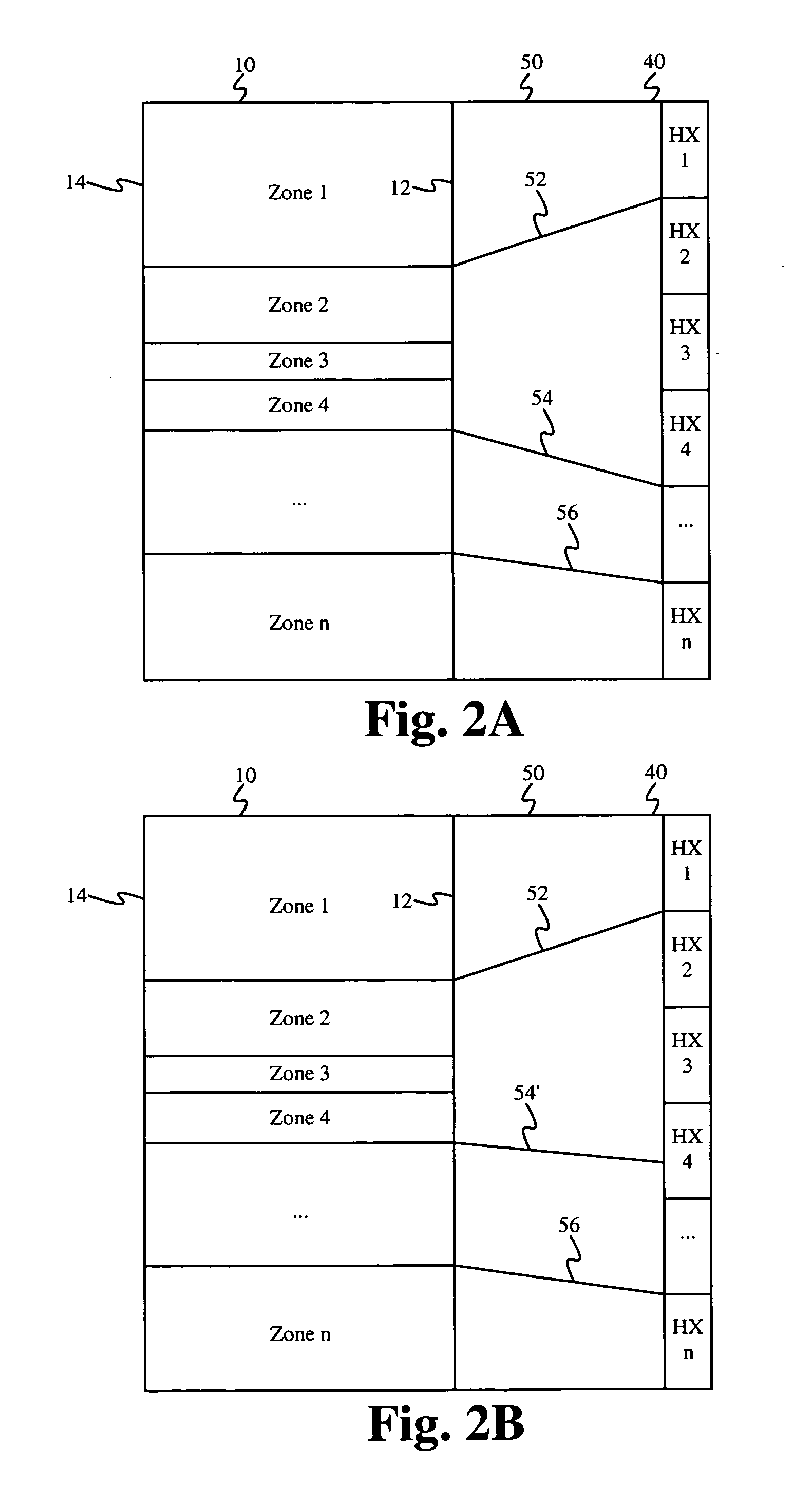
[0065]In FIG. 6, the heat exchangers and duct work are configured to direct air upward. In an alternative configuration, the heat exchangers and duct work are configured to direct air downward. FIG. 7 illustrates an isometric view of an electronics enclosure with an access mechanism. The access mechanism of FIG. 7 is configured similarly as the access mechanism of FIG. 6 except that the heat exchanges and duct work are configured to direct air downward. Specifically, the heat exchangers 322, 324, 326 replace the heat exchangers 222, 224, 226 of FIG. 6, and duct work 332, 334, 336 replaces duct works 232, 234, 236 of FIG. 6. Each of the heat exchangers 322, 324, 326 is coupled to fluid lines 340 for input and output of cooling fluid. The fluid lines 340 can be flexible or hard-plumbed. Air output from the back of the electronics enclosure 310 is directed to each of the heat exchangers 322, 324, 326 via the duct works 332, 334, 336, respectively. The heat exchangers 322, 324, 326 are ...
PUM
 Abstract
Description
Claims
Application Information