
Method and Apparatus for Providing polymer to be Used at Vacuum Infusion

a vacuum infusion and polymer technology, applied in the direction of chemistry apparatus and processes, sustainable manufacturing/processing, final product manufacturing, etc., can solve the problems of air pockets, difficult or impossible to remove, and ensure the complete distribution of polymer in the entire mould cavity, so as to reduce the time for filling the mould, and reduce the risk of dry spots

Active Publication Date: 2009-02-26
LM GLASSFIBER
View PDF2 Cites 28 Cited by
  • Summary
  • Abstract
  • Description
  • Claims
  • Application Information

AI Technical Summary

Benefits of technology

[0007]The object of the present invention is to provide a new and improved method of manufacturing a shell member of fibre composite material by means of vacuum infusion, where both the time for filling the mould, the curing time and the risk of dry spots can be reduced.

Problems solved by technology

Ensuring a complete distribution of the polymer in the entire mould cavity is, however, often difficult, and accordingly this often results in so-called dry spots, i.e. areas with fibre material not being sufficiently impregnated with resin.
Thus dry spots are areas where the fibre material is not impregnated, and where there can be air pockets, which are difficult or impossible to remove by controlling the vacuum pressure and possibly an overpressure at the inlet side.
This is a time-consuming and tiresome process.
In the case of large mould parts, staff have to stand on the vacuum bag, which is not desirable, especially not when the polymer has not hardened, as it can result in deformations in the inserted fibre material and thus in a local weakening of the structure.
Furthermore the infusion process has become more complicated, as the impregnation of large shell members, such as blades, requires control of the flow fronts to avoid dry spots, said control may e.g. include a time-related control of inlet channels and vacuum channels.
This increases the time required for drawing in or injecting polymer.
As a result the polymer has to stay liquid for a longer time, normally also resulting in an increase in the curing time.

Method used


Image

  • Method and Apparatus for Providing polymer to be Used at Vacuum Infusion
  • Method and Apparatus for Providing polymer to be Used at Vacuum Infusion
  • Method and Apparatus for Providing polymer to be Used at Vacuum Infusion

Examples


Embodiment Construction

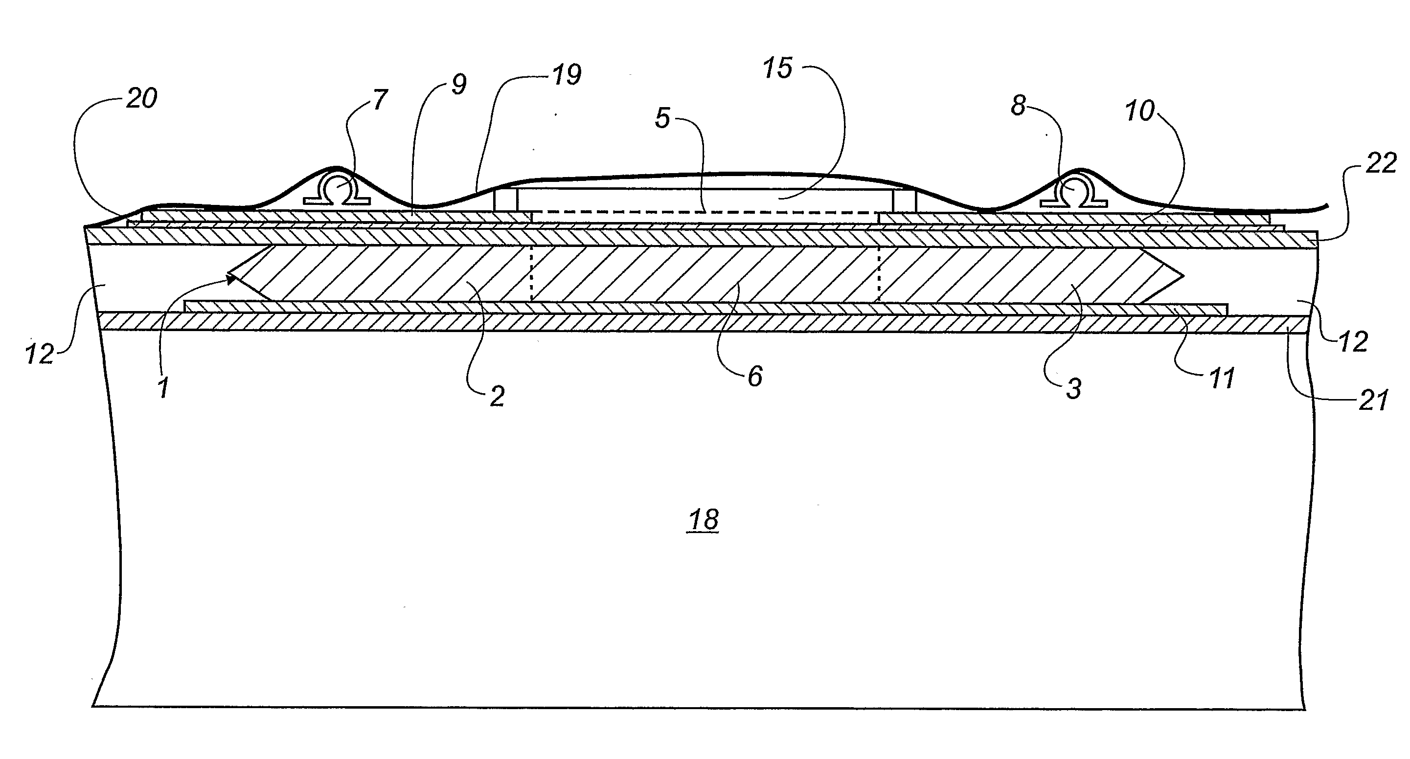
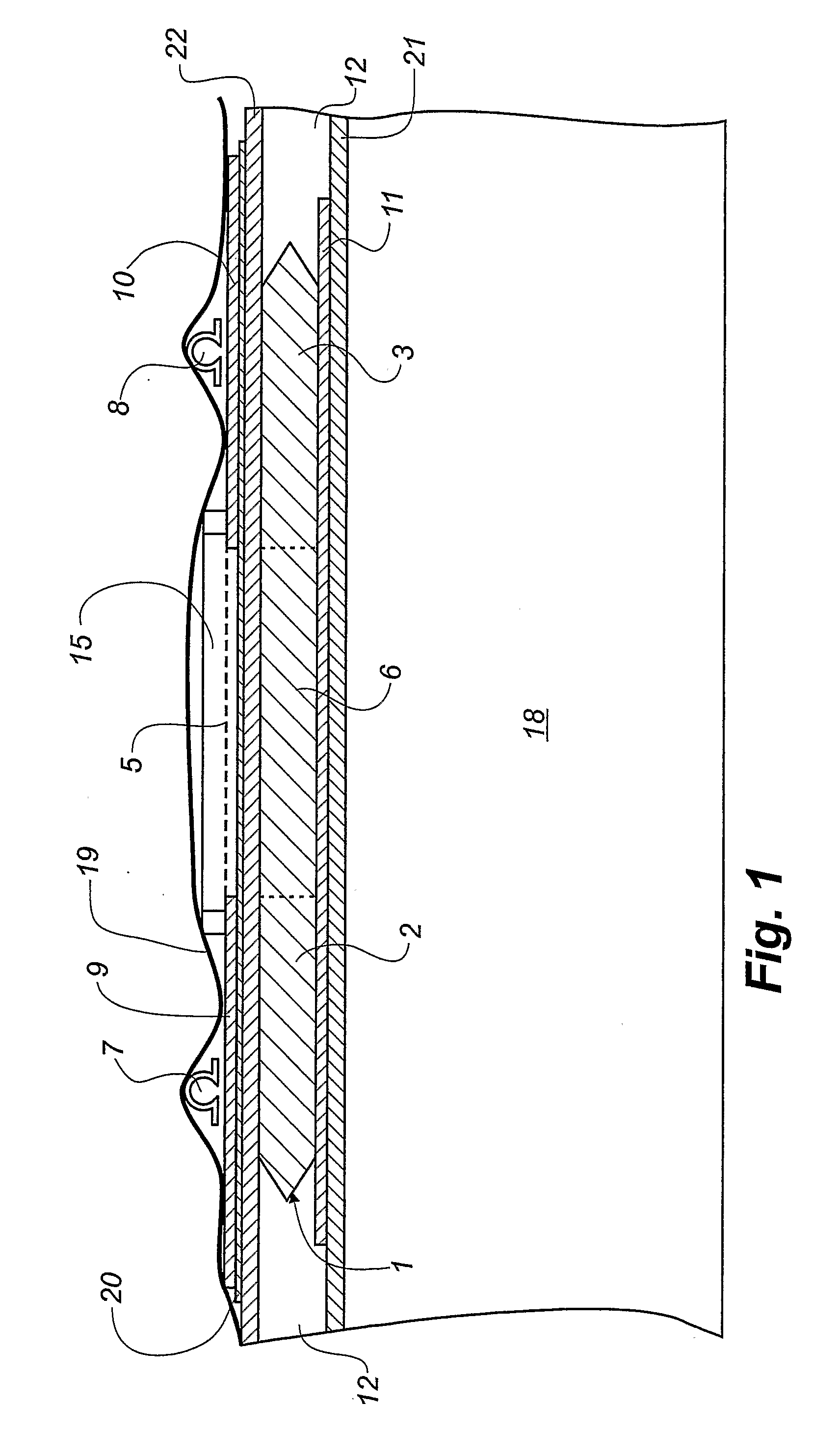
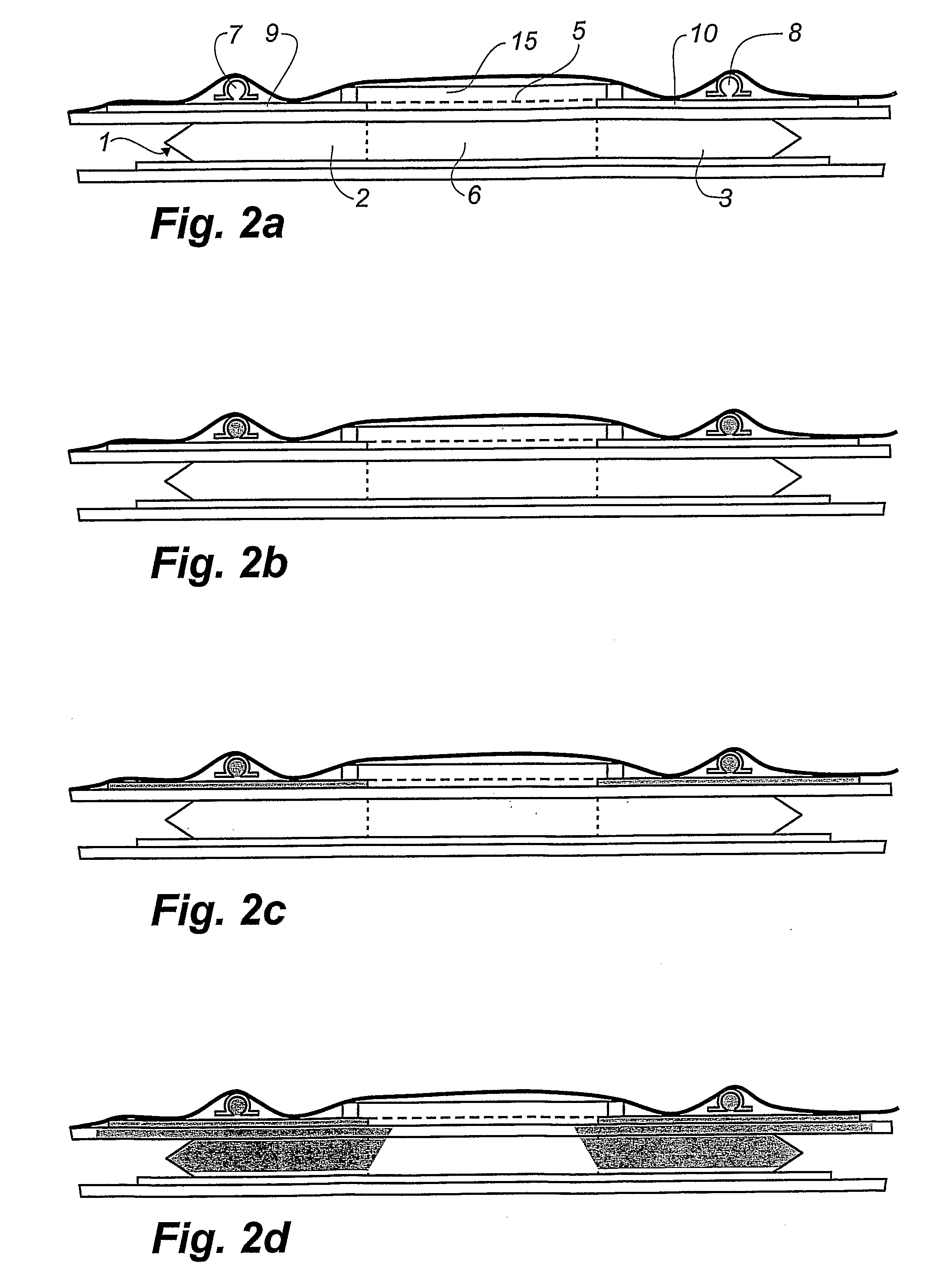
[0036]The section shown in FIG. 1 through a mould for manufacturing a blade shell half for a blade of a wind turbine by means of vacuum infusion shows a solid mould part 18 with a top side matching the exterior side of the finished blade shell half. For illustrative reasons the top side of said mould part 18 is shown as being plane, but it will typically be curved to the desired form of the blade shell half. First, a so-called gel coat is placed on the inner side of the mould part 18, said gel coat later on forming the outside of the finished blade shell half. Above the gel coat is placed a fibre material consisting of a plurality of lower, preferably thin, fibre layers 21, above which a lower distribution layer 11 is placed. A fibre insertion 1 is placed on top of the distribution layer 11 and the fibre layers 21, and next to said fibre insertion a filling material or sandwich material, such as balsa 12 or PVC foam, is placed.

[0037]Above the fibre insertion 1, in the shown embodime...


PUM

PropertyMeasurementUnit
Thicknessaaaaaaaaaa
Thicknessaaaaaaaaaa
Thicknessaaaaaaaaaa

Abstract

The invention relates to a method of producing a shell member of fibre composite material by means of vacuum infusion, where the fibre material is impregnated with liquid polymer, and applying a mould (18) with a mould cavity. In the mould cavity a lower distribution layer (11) is placed. A fibre insertion (1) including a plurality of fibre layers is placed above the lower distribution layer (11). A first upper distribution layer (9) and a second upper distribution layer (10) are placed at a transverse distance of each other above the fibre insertion, so that at least a part of the first distribution layer overlaps a first zone (2) of the fibre insertion (1), and at least a part of the second distribution layer overlaps a second zone (3) of the fibre insertion (1), the first zone (2) and the second zone (3) being separated by an intermediate zone (6) neither overlapping the first nor the second distribution layer (9, 10). A first inlet channel (7) is placed above the first distribution layer (9), and a second inlet channel (8) is placed on top of the second distribution layer (10). Above the intermediate zone (6) of the fibre insertion (1) a semi-permeable membrane (5) is placed, which may expand overlappingly over the first distribution layer (9) and / or the second distribution layer (10), and which is permeable to gasses and substantially impermeable to liquid polymer, said semi-permeable membrane (5) communicating with a vacuum source. Finally, in a manner known per se, a vacuum bag (19) is placed on top of the mould (18), which is evacuated of air by means of the vacuum source, and polymer is directed into the mould via the first and the second inlet channels (7, 8). The invention also relates to an apparatus for providing polymer for use with the method.

Description

TECHNICAL FIELD[0001]The present invention relates to a method of producing a shell member of fibre composite material by means of vacuum infusion, where the fibre material is impregnated with liquid polymer, and where a mould with a mould cavity is applied. Furthermore the invention relates to an apparatus for providing polymer to be used at vacuum infusion in connection with manufacturing preferably oblong shell members.[0002]Thus the invention relates to a method and an apparatus for producing fibre composite mouldings by means of VARTM (vacuum assisted resin transfer moulding), where liquid polymer, also called resin, is filled into a mould cavity, in which fibre material priorly has been inserted, as a vacuum is generated in the mould cavity hereby drawing in the polymer. The polymer can be thermoset plastic or thremoplast.PRIOR ART[0003]Vacuum infusion is a process used for moulding fibre composite mouldings, where uniformly distributed fibres, said fibres being rovings, i.e. ...

Claims


Application Information

Patent Timeline
IPC IPC(8): B29C70/44B29C48/76
CPCB29C70/547B29C70/443Y02P70/50
Inventor KOFOED, MICHAELHANSEN, TIM MOLLER
Owner LM GLASSFIBER
Learn More