Vacuum Infusion by Means of a Semi-Permeable Membrane

a semi-permeable membrane and vacuum technology, applied in the field of vacuum infusion by means of a semi-permeable membrane, can solve the disadvantage of placing the outermost layer, achieve the effect of reducing the time for preparing the filling process, reducing the time for forming the mold, and ensuring the quality of the liquid polymer

Active Publication Date: 2008-04-24
LM GLASSFIBER
View PDF4 Cites 11 Cited by
  • Summary
  • Abstract
  • Description
  • Claims
  • Application Information

AI Technical Summary

Benefits of technology

[0016] According to an advantageous embodiment, the central zone is 100 to 200 mm, 120 to 180 mm or 130 to 170 mm wide. It has turned out that such widths ensure achieving the intentional effect to the greatest possible extent.
[0017] Vacuum channels can be provided along the edges of the blade shell half. Hereby the parts of the blade shell half at each side of the main laminate are injected efficiently with liquid polymer.
[0018] According to a preferred embodiment, inlet channels are provided along the longitudinal edges of the semi-permeable membrane. Hereby the liquid polymer can easily flow to the distribution layer and continue into the main laminate.
[0019] According to a particularly advantageous embodiment, an oblong membrane bag with a front, a back, a central vacuum channel and two inlet channels is applied, said two Inlet channels extending on their respective sides of the vacuum channel, where the front opposite the vacuum channel is formed by the semi-permeable membrane and the front opposite the inlet channels is permeable to liquid polymer. As a result the time for preparing the process of filling the m

Problems solved by technology

A distribution layer with a high permeability does not contribute to the bending

Method used


Image

  • Vacuum Infusion by Means of a Semi-Permeable Membrane
  • Vacuum Infusion by Means of a Semi-Permeable Membrane
  • Vacuum Infusion by Means of a Semi-Permeable Membrane

Examples


Embodiment Construction

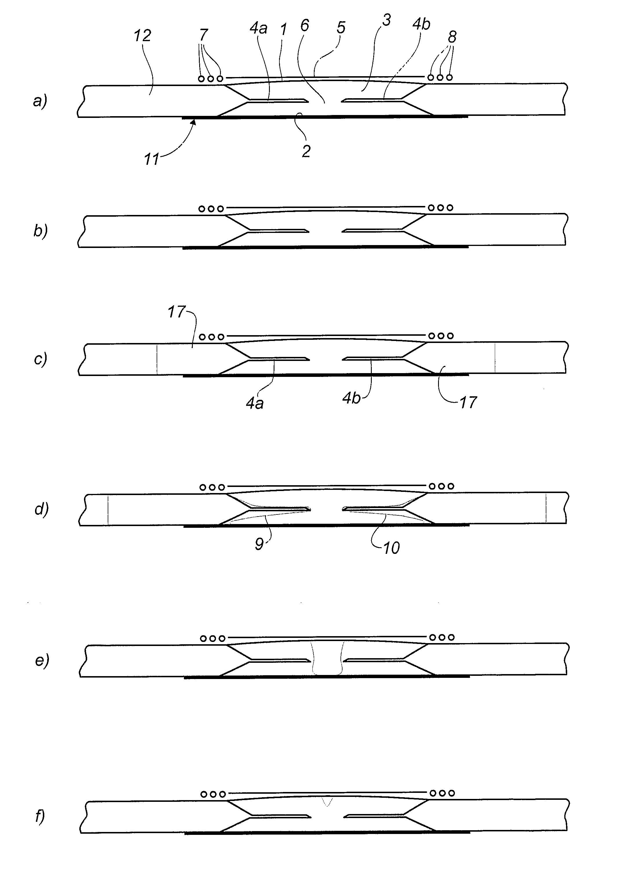
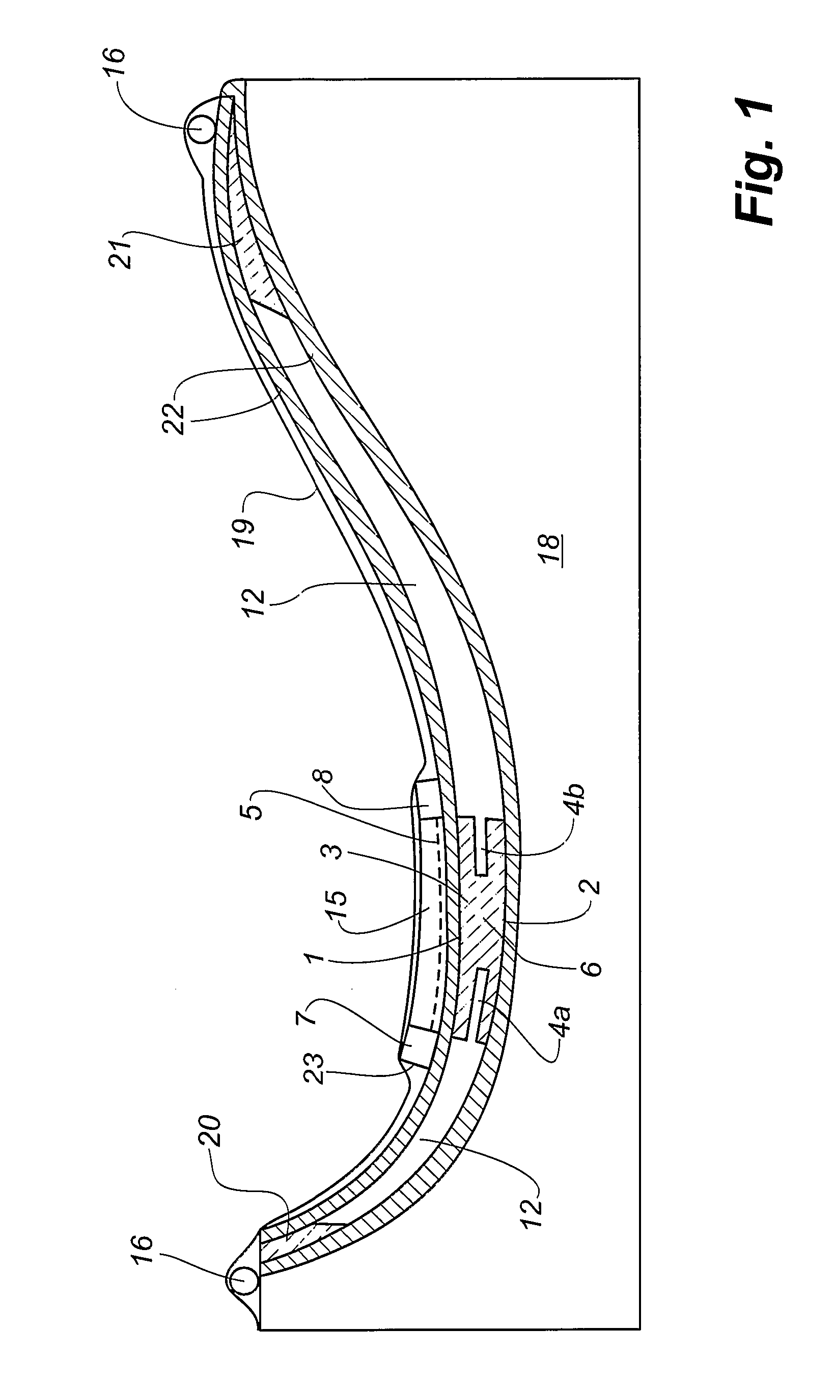
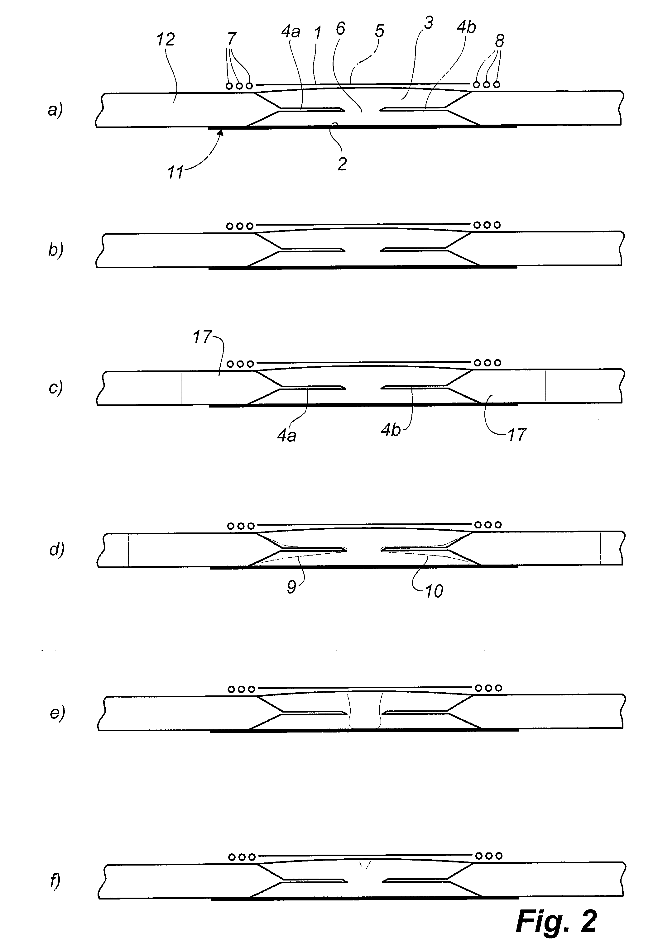
[0025] The cross section at view of FIG. 1 through a mould for manufacturing a blade shell half for a blade of a wind turbine by vacuum infusion shows a solid mould part 18 with a top side matching the exterior side of the completed blade shell half. First, a so-called gel coat is placed on the inner side of the mould part 18, said gel coat later on forming the outside of the completed blade shell half. Fibre material 3, 22 and balsa 12 are placed on top of the gel coat. The fibre Insertion 3 forming the main laminate of the blade is placed at the lowest part of the mould and includes a first lateral face 1 facing upwards, and a second lateral face 2 facing downwards. On top of the first lateral face 1 of the main laminate, a membrane bag 23 is placed, which is shown in greater detail in FIG. 3, and which includes a vacuum channel 15 with a semi-permeable membrane 5 pointing towards the main laminate 3, and two inlet channels 7, 8. Vacuum channels in the form of perforated tubes 16 ...


PUM

PropertyMeasurementUnit
Lengthaaaaaaaaaa
Lengthaaaaaaaaaa
Lengthaaaaaaaaaa

Abstract

Method of producing an oblong shell member made of fibre composite material by means of vacuum infusion, where the fibre material is impregnated with liquid polymer. A mould is applied with a mould cavity, in which a fibre insertion (3) with a first lateral face (1) and a second lateral face (2) is placed, and where said fibre insertion includes a plurality of fibre layers and a distribution layer (4), said distribution layer allowing a higher rate of flow for the liquid polymer than the fibre layers. A semi-permeable membrane (5) is placed opposite the first lateral face (1) of the fibre insertion, said semi-permeable membrane being substantially permeable to gasses and substantially impermeable to liquid polymer and further communicating with a vacuum source The distribution layer (4) is placed inside the fibre insertion (3) with fibre layers on both sides and is interrupted by a zone (6) opposite the semi-permeable membrane (5) Liquid polymer is directed via inlet channels (7, 8) to the distribution layer (4), thus creating a flow front (9, 10) between the distribution layer (4) and the second lateral face (2), said flow front moving through the central zone (6) towards the semi-permeable membrane (5)

Description

TECHNICAL FIELD [0001] The invention relates to a method according to the preamble of claim 1. [0002] Thus the invention relates to a method of producing fibre composite mouldings by means of VARTM (vacuum assisted resin transfer moulding), where liquid polymer, also called resin, is filled into a mould cavity, in which an insert of fibre material has been placed in advance, and where a vacuum is generated in the mould cavity hereby drawing in the polymer. The polymer can be thermoset or thermoplastic. BACKGROUND ART [0003] Vacuum infusion is a process used for moulding fibre composite mouldings, where uniformly distributed fibres are layered in one of the mould parts, said fibres being rovings, i.e. bundles of fibre bands, bands of rovings or mats, which are either felt mats made of single fibres or woven mats made of fibre rovings. The second mould part, which is often made of a resilient vacuum bag, is subsequently placed on top of the fibre material. By generating a vacuum, typi...

Claims


Application Information

Patent Timeline
IPC IPC(8): B29C70/54B29C70/44
CPCB29C70/546B29C70/443B29C70/44B29C70/54
Inventor HANSEN, TIM MOLLER
Owner LM GLASSFIBER
Why Eureka
Try Eureka