Bracket for mounting a guiding rail

a technology for mounting brackets and guiding rails, which is applied in the direction of washstands, door/window protective devices, lighting support devices, etc., can solve the problems of warped guiding rails upon mounting, difficulty in positioning and aligning such brackets, and inability to mount guiding rails, etc., to achieve less cumbersome assembly and operation, and relatively inexpensive

Active Publication Date: 2009-03-05
HUNTER DOUGLAS IND BV
View PDF6 Cites 8 Cited by
  • Summary
  • Abstract
  • Description
  • Claims
  • Application Information

AI Technical Summary

Benefits of technology

[0006]Accordingly it is an object of the present invention to overcome or ameliorate at least one of the disadvantages of the prior art. It is also an object of the present invention to provide alternative structures which are less cumbersome in assembly and operation and which moreover can be made relatively inexpensively. Alternatively it is an object of the invention to at least provide the public with a useful choice.

Problems solved by technology

While the use of plural brackets has offered a more than adequate attachment for guiding rails, it has at times been somewhat more difficult to position and align such brackets prior to fixing these to a wall surface.
This problem has been particularly apparent when three or more brackets are used in mounting a single guiding rail.
Especially when an intermediate bracket is misaligned, it is either impossible to mount the guiding rail, or worse the guiding rail is warped upon mounting.

Method used


Image

  • Bracket for mounting a guiding rail
  • Bracket for mounting a guiding rail
  • Bracket for mounting a guiding rail

Examples


Embodiment Construction

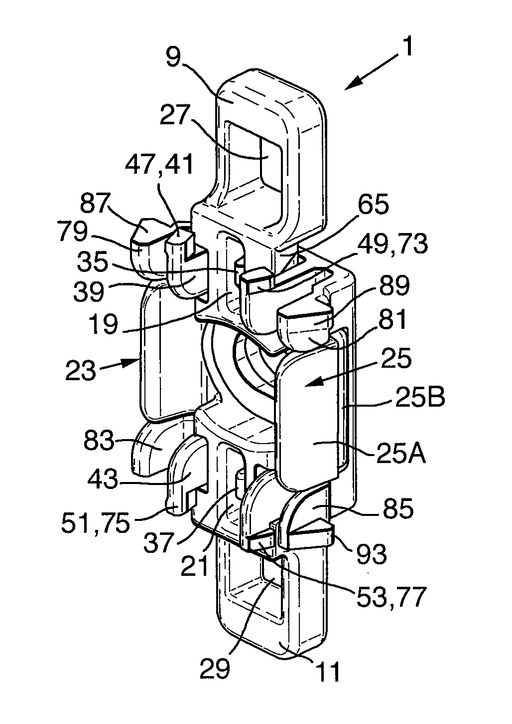
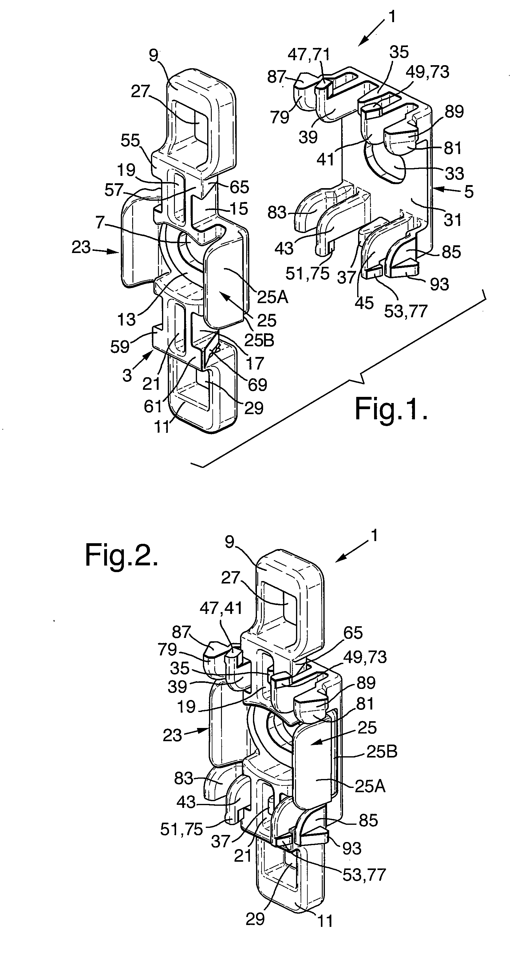
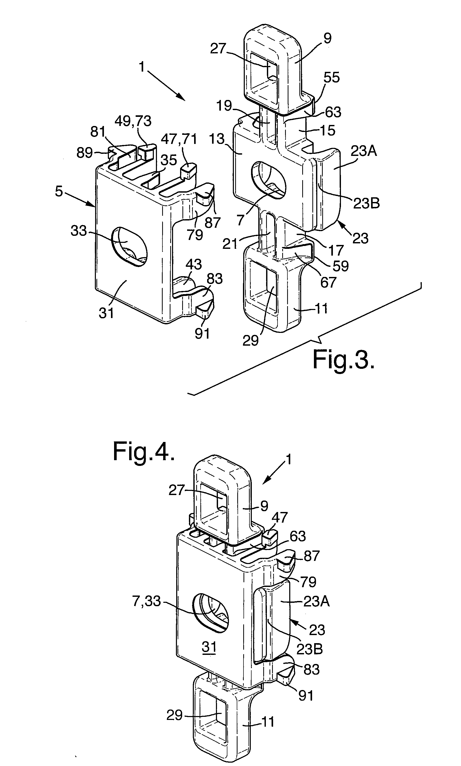
[0021]Referring first to FIGS. 1 to 4, which show an embodiment of the mounting bracket 1 according to the invention, it is seen that the bracket 1 consists of a body part 3 and a clip part 5. The body part 3 has a mounting hole 7, to accept a mounting screw (not shown but conventional). The body part 3 further has first and second outer support legs 9, 11 connected to a main body 13 of the body part 3, which carries the mounting hole 7, by first and second transition portions 15, 17. Each of the respective first and second transition portions 15, 17 has a respective first or second central slot 19, 21. The main body 13 has opposite first and second snap flanges 23, 25. Each of the first and second snap flanges 23, 25 is formed by a sloped section 23A, 25A and a holding ridge 23B, 25B. The first and second outer support legs 9, 11 each have a respective first support leg aperture 27 and a second support leg aperture 29.

[0022]The clip part 5 has a web portion 31 which is provided wit...


PUM


Abstract

Bracket for mounting a guiding rail to a support surface. The mounting bracket includes a body part having a main body defining a mounting hole and opposite parallel first and second snap flanges. The bracket further has a clip part for engaging its body part and has at least one resilient tongue and at least one resilient arm extending from the clip part in alignment with the first and second snap flanges. The invention also relates to the combination of the mounting bracket and a guiding rail, as well as to a method for mounting a plurality of the brackets and the guiding rail to a mounting surface.

Description

CROSS REFERENCE TO RELATED APPLICATION[0001]This application claims priority to European Patent Application No. 07016893.5 filed on 29 Aug. 2007, and such application is hereby incorporated by reference as if fully disclosed herein.BACKGROUND OF THE INVENTION[0002]1. Field of the Invention[0003]The invention relates to a bracket for mounting a guiding rail for an architectural covering, such as a roller blind or screen.[0004]2. Description of the Relevant Art[0005]French patent document FR 2266790 discloses a mounting element for fixing to a surface surrounding an architectural opening. The known mounting element has clipping arms which can engage detent means on a guiding rail element. For this arrangement to be reasonably successful it has been necessary to provide the mounting element with a longitudinal length substantially similar to the length of the guiding rail. In the interest of material savings it has become popular to mount such guiding rails from a plurality of smaller ...

Claims


Application Information

Patent Timeline
Patent Type & Authority Applications(United States)
IPC IPC(8): A47B96/06
CPCE06B2009/587E06B9/58
Inventor GARMYN, TOMAS M.A.H.
Owner HUNTER DOUGLAS IND BV
Why Eureka
Try Eureka