Tool, method, and system for in-line inspection or treatment of a pipeline

a pipeline and inline inspection technology, applied in the direction of pipe protection, mechanical equipment, instruments, etc., can solve the problems of limited capabilities, inaccessible inspection of many pipelines for oil and gas transportation, and inability to meet the needs of inspection, etc., to achieve the effect of less cumbersome assembly and operation, and relatively inexpensive production

Active Publication Date: 2015-11-19
ROENTGEN TECHNISCHE DIENST BV
View PDF12 Cites 28 Cited by
  • Summary
  • Abstract
  • Description
  • Claims
  • Application Information

AI Technical Summary

Benefits of technology

[0028]In a more general sense it is thus an object of the invention to overcome or reduce at least one of the disadvantages of the prior art. It is also an object of the present invention to provide alternative solutions which are less cumbersome in assembly and operation and which moreover can be made relatively inexpensively. Alternatively it is an object of the invention to at least provide a useful alternative.

Problems solved by technology

Many pipelines for transport of oil and gas are not directly accessible for inspection because they are buried (on shore) or submerged (off shore).
Also for smaller diameter pipes tools are available, like 4″, 8″ or 12″, but these have limited capabilities.
Obviously, smaller diameter pipes are more difficult to inspect from the inside because the inspection tool, including sensors, electronics and mechanics, must fit inside the pipe diameter.
However, the exact inner pipe diameter may not always be known accurately, for example for older installations.
A significant part of pipeline failures (possibly more than 50%) are related to difficult to inspect pipe segments with available pigging tools, hence these pipelines are often referred to as ‘difficult to pig pipelines’ or even ‘unpiggable pipelines’.

Method used


Image

  • Tool, method, and system for in-line inspection or treatment of a pipeline
  • Tool, method, and system for in-line inspection or treatment of a pipeline
  • Tool, method, and system for in-line inspection or treatment of a pipeline

Examples


Embodiment Construction

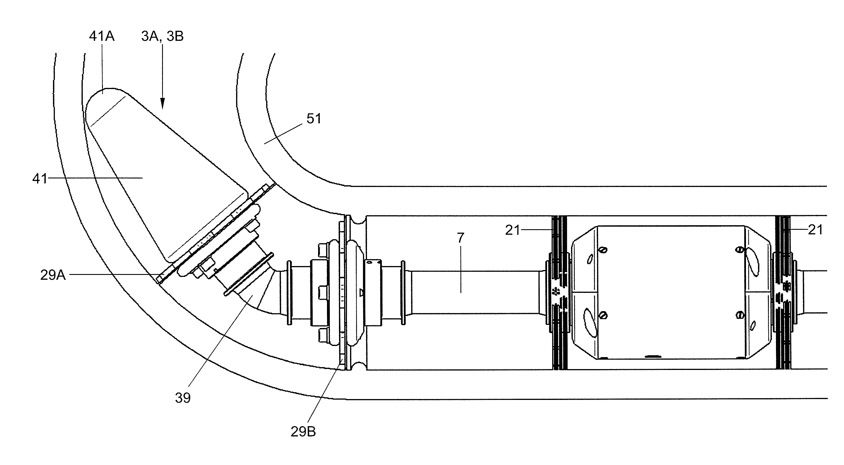
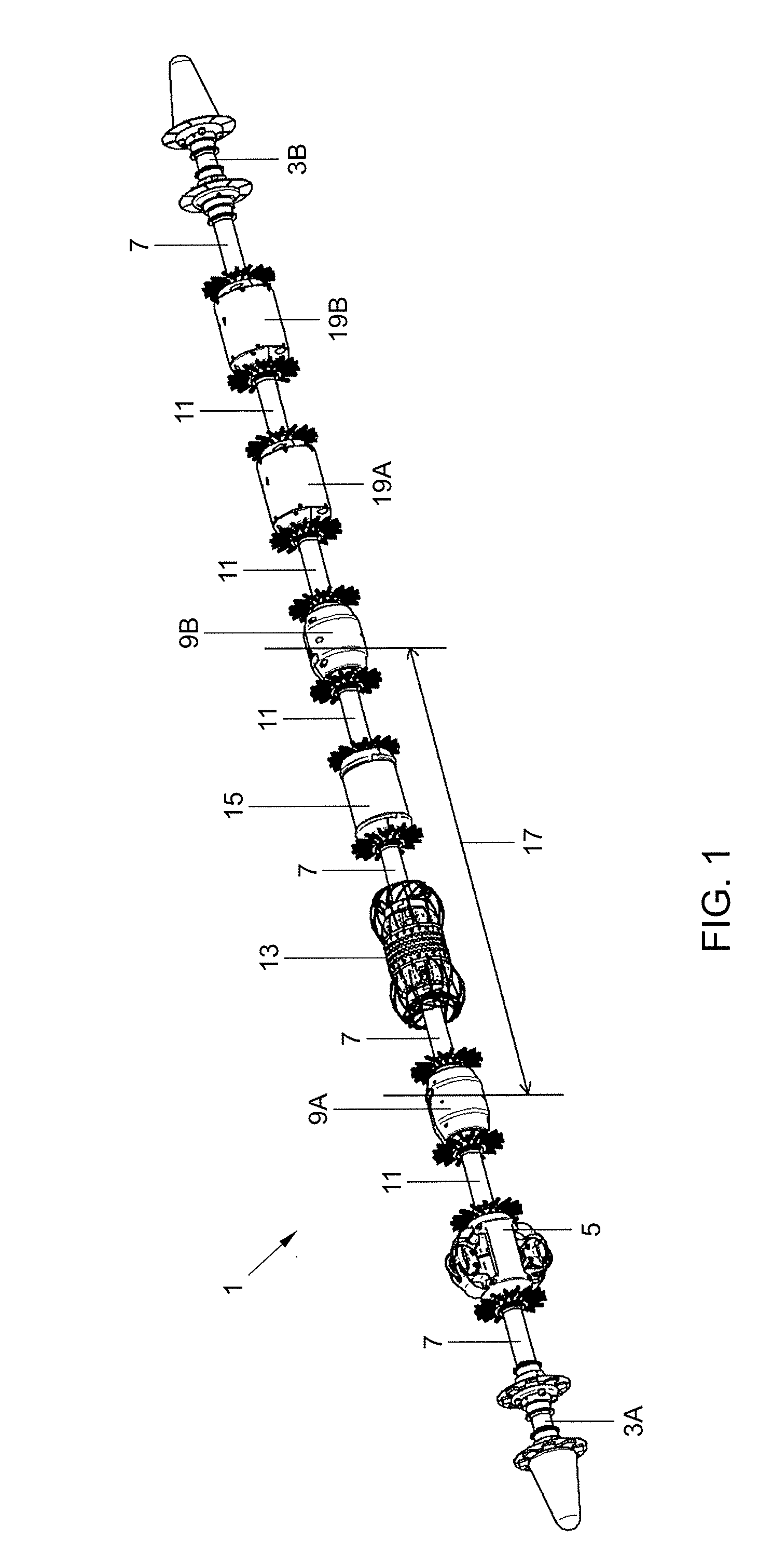
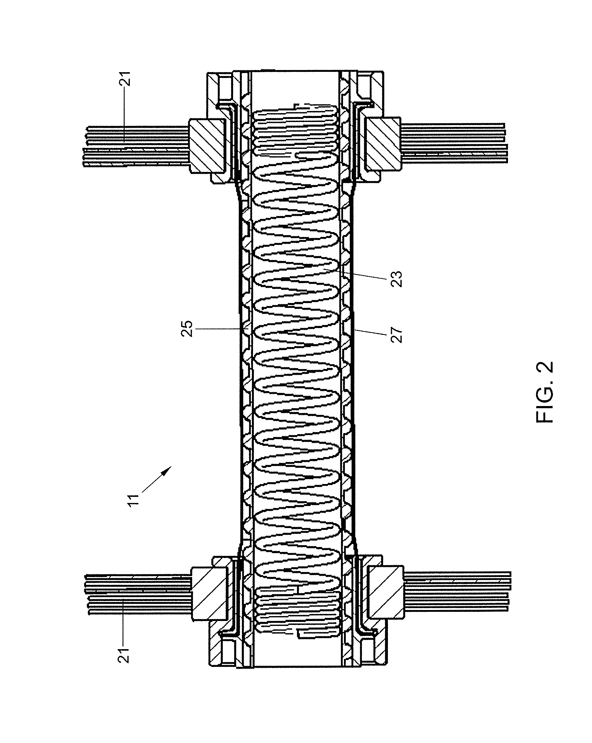
[0052]Referring to FIG. 1 a main assembly of a tool 1 is shown. In FIG. 1 a main assembly of a tool 1 for in-line inspection of a pipeline is shown. Starting from the left hand side of FIG. 1 a first traction module 3A is followed by an encoder module 5. The encoder module 5 is flexibly connected to the first traction module 3A in an articulated fashion by a first type of flexible connection element 7. The encoder module 5 is followed by a first connector module 9A, which in turn is connected to the encoder module 5 through a second type of flexible connecting element 11. The second type of flexible connecting element 11 differs from the first type of flexible connecting element 7 in having a bristle at each of its opposite longitudinal ends. The first type of flexible connecting element 7 only has a bristle on one of its longitudinal ends. The first connector module 9A accommodates electrical connection and forms a barrier between oil filled pressure compensated modules and non-pre...


PUM

PropertyMeasurementUnit
inner diameteraaaaaaaaaa
diameteraaaaaaaaaa

Abstract

A tool, method, and system for in-line inspection or treatment of a pipeline, with the tool including a first traction module on a first longitudinal end, and a second traction module on a second end. The tool includes at least one work module, such as an encoder module and/or an ultrasonic testing module, which is positioned between the first and second traction modules. A plurality of flexible connecting elements each interconnect one of the first and second traction modules for articulation to the at least one work module. Each of the first and second traction modules has at least one sealing element that causes propulsion in response to a fluid flow in a pipeline to be inspected or treated in one direction and allows relatively unhindered passing of the fluid flow in an opposite direction.

Description

[0001]The invention relates to a tool for in-line inspection or treatment of a pipeline, a method of inspecting or treating a pipeline, and a pipeline system including the tool for performing the method.BACKGROUND OF THE INVENTION[0002]Many pipelines for transport of oil and gas are not directly accessible for inspection because they are buried (on shore) or submerged (off shore). Several tools are available for In-Line-Inspection (ILI) of pipelines with a diameter of e.g. 16″, 24″ or larger. Also for smaller diameter pipes tools are available, like 4″, 8″ or 12″, but these have limited capabilities. These tools perform ultrasonic, magnetic or eddy current examination of a pipe from the inside and are often referred to as ‘pigs’. The collected data is used for assessment of the integrity and fitness for service of the pipeline.[0003]In general the following criteria identify pipes which are difficult to inspect, especially in combination:[0004]small diameter (less than 200 mm diamet...

Claims


Application Information

Patent Timeline
Patent Type & Authority Applications(United States)
IPC IPC(8): F16L55/18F16L58/04G01N29/04F16L57/00
CPCF16L55/18F16L57/00G01N2291/044G01N29/043F16L58/04F16L55/265F16L55/38F16L55/40G01N29/225F16L2101/30G01N2291/0234G01N2291/02854G01N2291/2636G01N2291/0258
Inventor VAN NIE, RONALD ANTONIEEVERS, RUUDDROOGERS, GERRIT JAN
Owner ROENTGEN TECHNISCHE DIENST BV
Why Eureka
Try Eureka