Orthodontic appliance

a technology for orthodontics and appliances, applied in the field of orthodontic appliances, can solve the problems of further shortening the treatment period, and achieve the effects of shortening the treatment period, and promoting the orthodontic

Inactive Publication Date: 2009-03-05
PANASONIC HEALTHCARE HLDG CO LTD
View PDF51 Cites 49 Cited by
  • Summary
  • Abstract
  • Description
  • Claims
  • Application Information

AI Technical Summary

Benefits of technology

[0009]In order to solve the above problems, an object of the present invention is to provide an orthodontic appliance which can align teeth within a shorter period of time than usual without using braces including an orthodontic wire and brackets.
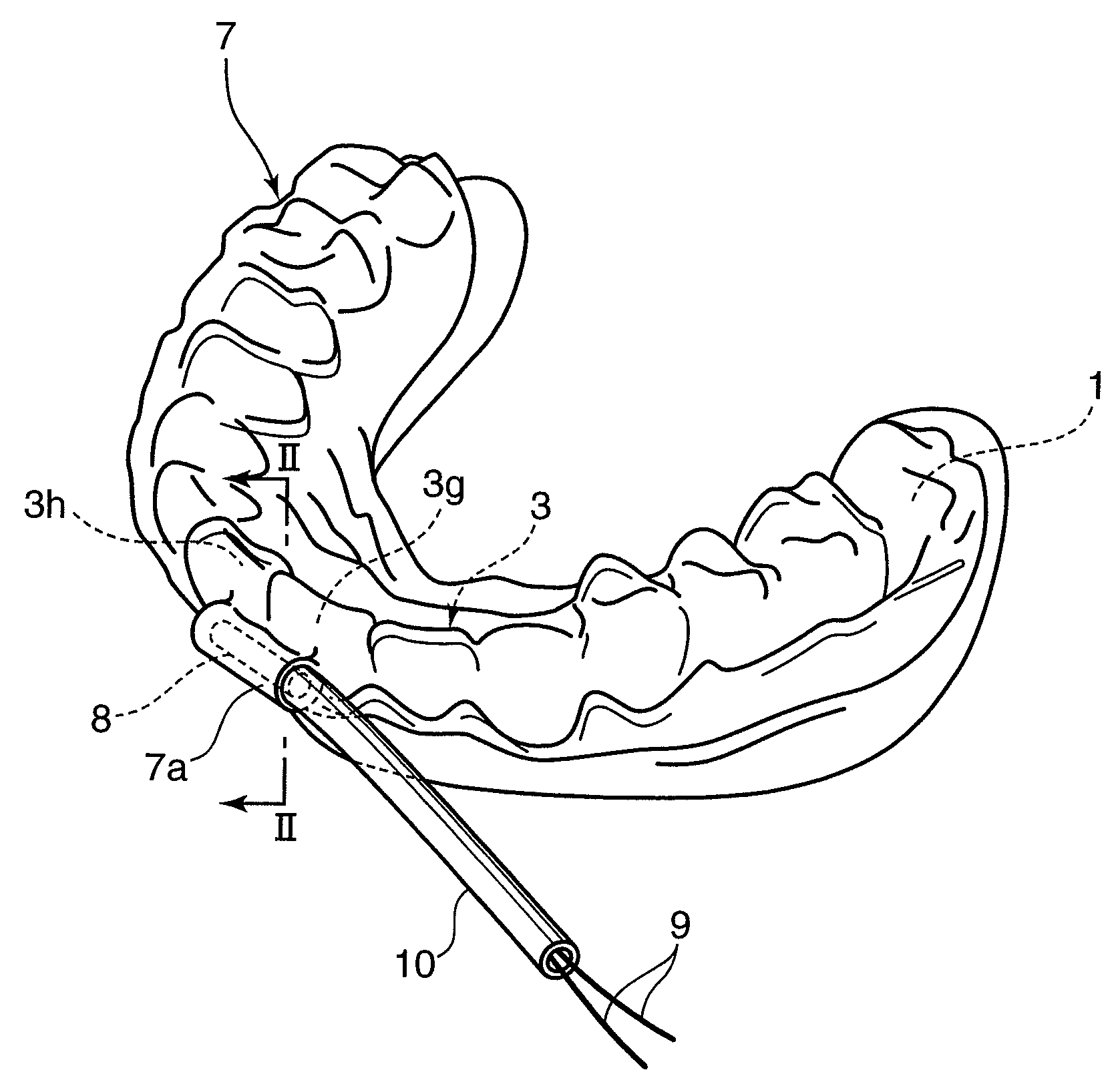
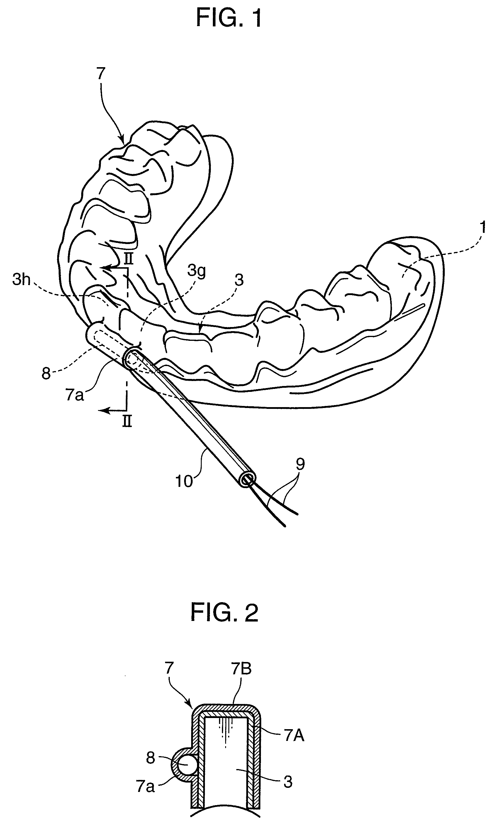
[0010]In order to solve the above problems, an orthodontic appliance according to the present invention comprises a dental mouthpiece mountable on the teeth, and a vibrating element. The dental mouthpiece is so shaped as to apply a biasing force in an aligning direction to the tooth to be aligned while being mounted on the teeth. The vibrating element is attached to the dental mouthpiece, generates mechanical vibration and applies the vibration to the tooth to be aligned, thereby promoting an orthodontic effect.
[0011]With this appliance, teeth alignment within a short period of time can be realized only by mounting the dental mouthpiece on the teeth. Specifically, the shape of the dental mouthpiece mounted on the teeth applies a suitable aligning force, i.e. a static biasing force in the aligning direction to the tooth to be aligned in the teeth and, in addition, the vibrating element attached to the dental mouthpiece applies the vibration to the tooth to be aligned, whereby the alignment of the teeth by the aligning force is promoted to shorten a period of orthodontic treatment.
[0012]Thus, according to the present invention, the orthodontic effect can be promoted only by the mounting of the dental mouthpiece and the operation of the vibrating element attached to the dental mouthpiece without using braces including an orthodontic wire and brackets. This dental mouthpiece may be mounted on the teeth only during the operating period of the vibrating element or may be mounted during other periods. If this dental mouthpiece is mounted for a longer period of time, the application period of the above biasing force is extended, thereby further shortening the treatment period.

Problems solved by technology

If this dental mouthpiece is mounted for a longer period of time, the application period of the above biasing force is extended, thereby further shortening the treatment period.

Method used


Image

  • Orthodontic appliance
  • Orthodontic appliance
  • Orthodontic appliance

Examples


fifth embodiment

[0075]FIG. 8 shows a dental mouthpiece 7-1 according to the The dividing portions of this dental mouthpiece 7-1 are cutout portions 7p. These cutout portions 7p are formed by cutting out tooth crown portions of the dental mouthpiece 7-1 except at the part corresponding to the teeth 3g, 3h to be aligned. For example, elliptical cutouts are made in the tooth crown portions for teeth 3c to 3e, 3j to 3l in FIG. 8. Tooth root portions 7q left in the dental mouthpiece 7-1 at the parts where the cutout portions 7p are formed integrally connect parts before and after the cutout portions 7p.

sixth embodiment

[0076]FIG. 9 shows a dental mouthpiece 7-2 according to the The dividing portions of this dental mouthpiece 7-2 are also cutout portions 7p. These cutout portions 7p are formed by cutting out tooth root portions of the dental mouthpiece 7-2 except at the part corresponding to the teeth 3g, 3h to be aligned. For example, elliptical cutouts are made in the tooth root portions for the teeth 3c to 3e, 3j to 3l in FIG. 9. Tooth crown portions 7r left in the dental mouthpiece 7-2 at the parts where the cutout portions 7p are formed integrally connect parts before and after the cutout portions 7p.

[0077]In the dental mouthpieces 7-1, 7-2, the vibrating actuator 8 for generating mechanical vibration is stored at the part corresponding to the teeth 3g, 3h to be aligned, and the cutout portions (dividing portions) 7p for suppressing the transmission of the mechanical vibration are formed in the parts other than the one corresponding to the teeth 3g, 3h to be aligned. This enables the partial...

seventh embodiment

[0080]FIG. 10 shows a dental mouthpiece 7-3 according to the The dividing portions of this dental mouthpiece 7-2 are slit portions 7s formed in parts of the dental mouthpiece 7-3 except a part corresponding to the teeth 3g, 3h to be aligned. These slit portions 7s are formed in parts between the teeth 3f, 3g and between the teeth 3h, 3i in FIG. 10, and parts before and after the respective slit portions 7s are integrally connected. The right slit portions 7s in FIG. 10 extend from a tooth root side toward a tooth crown side, whereas the left slit portion 7s extends from the tooth crown side toward the tooth root side. In the present invention, the directions of these slit portions are not limited.

[0081]The dental mouthpiece 7-3 according to this seventh embodiment can achieve functions and effects similar to those of the dental mouthpieces 7-1, 7-2.


PUM


Abstract

The present invention aims to provide an orthodontic appliance capable of aligning teeth within a shorter period of time than usual without using braces including an orthodontic wire and brackets. This appliance is provided with a dental mouthpiece mountable on teeth and a vibrating element. The dental mouthpiece is so shaped as to apply a biasing force in an aligning direction to a tooth to be aligned in the teeth while being mounted on the teeth. The vibrating element is attached to the dental mouthpiece, generates mechanical vibration and applies the vibration to the tooth to be aligned, thereby activating the bone remodeling of a target tooth and an alveolar bone to promote an orthodontic effect.

Description

TECHNICAL FIELD[0001]The present invention relates to an orthodontic appliance.BACKGROUND ART[0002]An orthodontic appliance equipped with an orthodontic wire to be mounted on teeth has been conventionally known. An elastic restoring force of the orthodontic wire acts as a constant static load on the teeth to correct teeth malalignment or crossbite. In other words, the orthodontic appliance is based on the principle of aligning the teeth by gradually deforming an alveolar bone supporting the teeth in the gum (bone reconstruction, bone remodeling) through the application of a constant force to the teeth.[0003]However, the teeth alignment using the orthodontic wire takes a very long time (fastest six months, normally several years) until an orthodontic treatment is finished. Such a long treatment period increases burdens on patients, causing them to give up easily.[0004]In order to shorten a period of such an orthodontic treatment, technology of giving a vibration force to the teeth ha...

Claims


Application Information

Patent Timeline
Patent Type & Authority Applications(United States)
IPC IPC(8): A61C7/08
CPCA61C7/00A61C7/006A61C13/20A61C7/08A61C7/008
Inventor YAMAMOTO, TERUKOKAMIOKA, HIROSHIADACHI, TAIJIFUKUSHIMA, SHOGOSAKIMURA, TAKUMI
Owner PANASONIC HEALTHCARE HLDG CO LTD
Why Eureka
Try Eureka