Orthodontic bracket and manufacturing method thereof

A technology for orthodontic brackets and manufacturing methods, applied in the field of orthodontics, can solve the problems of high price, complex structure, and high cost, and achieve the effects of convenient manufacturing, increased height, and low cost

Active Publication Date: 2018-03-09
ZHEJIANG SHINYE MEDICAL TECH CORP LTD
View PDF7 Cites 0 Cited by
  • Summary
  • Abstract
  • Description
  • Claims
  • Application Information

AI Technical Summary

Problems solved by technology

[0003] In the early stage of bracket correction currently used, the ligation rubber ring or the ligation steel wire is ligated on the ligation wing of the bracket, and force is directly applied to the arch wire, which produces a large pressure on the arch wire and hinders the normal movement of the arch wire, thus Affected orthodontic effect of teeth
At present, there are many kinds of self-locking brackets on the market, including two series of active type and passive type, but they are large in size, especially higher than ordinary brackets, and their structures are more complicated, difficult to manufacture, high in cost, and expensive

Method used


Image

  • Orthodontic bracket and manufacturing method thereof
  • Orthodontic bracket and manufacturing method thereof
  • Orthodontic bracket and manufacturing method thereof

Examples


Embodiment

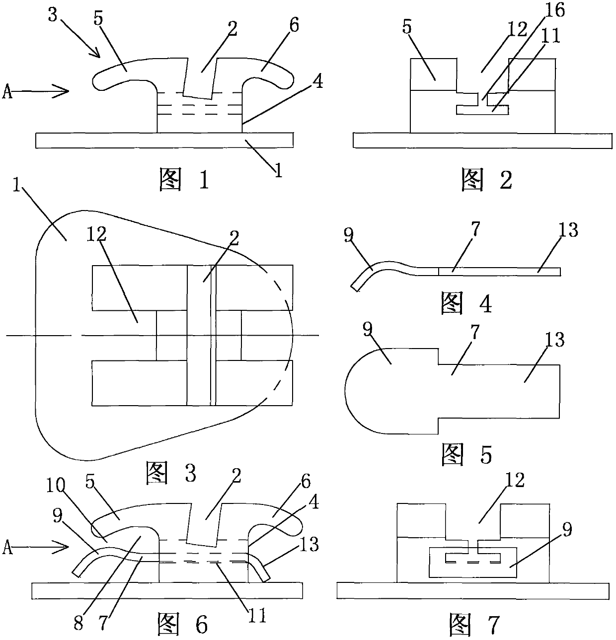
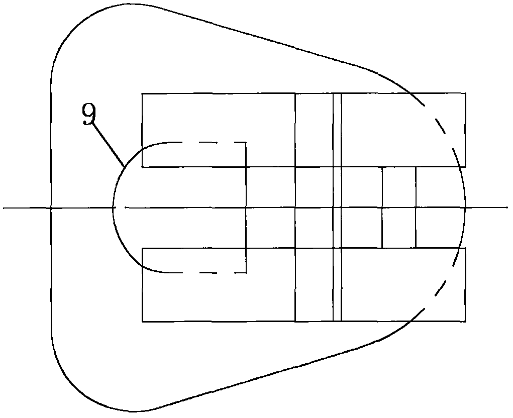
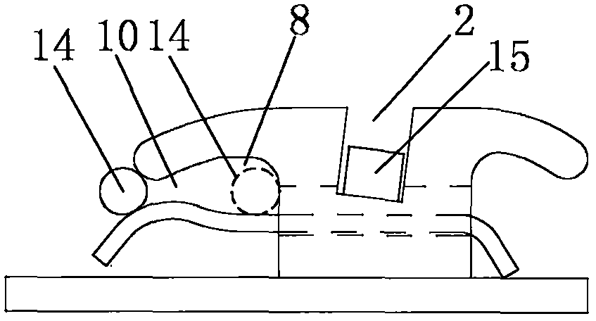
[0041] Embodiment: the orthodontic bracket of the present embodiment is a double-wing hook bracket, such as Figure 1-9 As shown, the bracket 3 includes a bracket body 4 with a mesh bottom 1 and a main archwire groove 2, and a bracket opening 12 is arranged at the intersection of the main archwire groove 2, and the main archwire groove in the bracket body 4 2 Ligating wings 5 ​​and 6 are arranged on both sides, and the bracket opening 12 is intersected with the main archwire groove 2. The bracket opening 12 and the main archwire groove 2 divide the ligation wings 5 ​​and 6 into four separate pieces, An elastic reed 7 is provided under the ligature wing 5 on one side, and an auxiliary archwire groove 8 is formed between the reed 7 and the ligature wing 5 , and the reed head 9 is connected to the ligature wing 3 A notch 10 is left between the edges for the secondary arch wire to slide into.

[0042] Specifically, the size of the notch 10 of the auxiliary archwire groove 8 is sm...

Embodiment 2

[0046] Embodiment 2: The principle of this embodiment is basically the same as that of Embodiment 1, the difference is that, as Figures 11-17 As shown, the bracket in this embodiment is a single-wing hook bracket. Because the tooth width of the lingual side is smaller than that of the labial side, it is better to use a single-wing double groove when correcting the lingual side. The head 9 of the reed 7 is bent only once, ie in the direction away from its adjacent ligating wing 5 . Note: One bend and multiple bends are related to the torque angle of the bracket.


PUM


Abstract

The invention discloses an orthodontic bracket for teeth and a manufacturing method thereof. The bracket includes a bracket body with a main archwire groove, and ligature wings are arranged on both sides of the main archwire groove in the bracket body. The feature is: an elastic reed is provided under the ligating wing on one side, a secondary archwire groove is formed between the reed and the ligating wing, and a gap between the head of the reed and the edge of the ligating wing There is a notch for the secondary archwire to slide into. The bracket of the present invention has double archwire grooves, and the auxiliary archwire grooves utilize the space below the ligature wings on the bracket body, wherein a reed is provided on the lower part of one ligature wing, and the gap between the ligature wing and the reed is The auxiliary arch wire groove is formed in the area, and the height of the bracket body is not increased, which makes the patient more comfortable and makes the bracket less likely to fall off. It is more convenient and reliable than the self-locking bracket with the main arch wire as self-locking; at the same time, in the later stage of orthodontics, due to the effect of double arch wires, orthodontics is faster and more efficient.

Description

technical field [0001] The invention relates to the technical field of dental orthodontics, in particular to a dental orthodontic bracket and a manufacturing method thereof. Background technique [0002] At present, in the process of orthodontic treatment of oral teeth, the orthodontic bracket is fixed on the tooth surface, and the arch wire passes through the arch wire slot (also known as the square wire slot) on the bracket, and is bound by a rubber ring or a steel wire. The arch wire is directly tied to the bracket ligation wing, and the correction force of the arch wire is transmitted to the teeth through the bracket, so that the teeth can move as expected, so as to achieve the purpose of correcting the teeth. [0003] In the early stage of bracket correction currently used, the ligation rubber ring or the ligation steel wire is ligated on the ligation wing of the bracket, and force is directly applied to the arch wire, which produces a large pressure on the arch wire an...

Claims


Application Information

Patent Timeline
Patent Type & Authority Patents(China)
IPC IPC(8): A61C7/30
Inventor 王光良
Owner ZHEJIANG SHINYE MEDICAL TECH CORP LTD
Why Eureka
Try Eureka