Orthodontic Treatment Bracket

a treatment bracket and orthodontic technology, applied in the field of medical devices, can solve the problems of limited correction effect of clinically used orthodontic brackets, poor overall treatment effect, and relatively long correction period, so as to shorten the treatment process and improve tooth occlusion

Inactive Publication Date: 2016-10-27
ZHAO XILIN +1
View PDF14 Cites 0 Cited by
  • Summary
  • Abstract
  • Description
  • Claims
  • Application Information

AI Technical Summary

Benefits of technology

[0044](1) The present invention makes improvement on the groove structure of bracket; switching between the two different contact modes of the archwire and the bracket groove is realized by flexibly controlling the length of the groove with the extender, thus satisfying the different requirements for friction in different clinical treatment stages. During the position adjustment, the groove is relatively short, and the archwire and bracket groove is in the point contact state with low friction, which is favorable for teeth movement, thereby shortening the course of treatment; during the orientation adjustment, the groove is relatively long, the archwire and bracket groove is in the surface contact state with high friction, which is favorable for the expression of the three-dimensional orientation data of the bracket and for controlling and adjusting the three-dimensional orientation of teeth and improving orthodontic effect.
[0045](2) The other technical protocol of the present invention is an orthodontic treatment bracket with double grooves, whose mesial groove has an extender. The distance between the mesial groove and the distal auxiliary groove of the double groove bracket is d=0.086-0.196 inches, much greater than that of current technology. The distal auxiliary groove is relatively far from the center of resistance of tooth movement, so the orthodontic force can quickly realize teeth tipping movement through filamentary light force, which can accelerate the position adjustment. The mesial groove is close to the center of resistance of tooth movement, thus the elastic force applied by the correction archwire is also close to the center of resistance, realizing the stable movement of all the teeth; this mode of force application can effectively control the movement of teeth in three directions, improve the effect of orientation adjustment and shorten the duration thereof.

Problems solved by technology

Under the current technology, the corrective effect of clinically used orthodontic brackets is limited, the correction period is relatively long and the overall treatment effect is poor.
No doubt the “point contact” can reduce friction, making it easier to move the teeth during the position adjustment, but the “point contact” also means that the correction archwire cannot fully fit with the bracket during the orientation adjustment or effectively adjust the three-dimensional orientation of teeth, thus the treatment effect is limited.
This leads to a big friction between the archwire and the bracket, thus making the teeth harder to move and the treatment duration longer in the position adjustment procedure.

Method used


Image

  • Orthodontic Treatment Bracket
  • Orthodontic Treatment Bracket
  • Orthodontic Treatment Bracket

Examples


embodiment 1

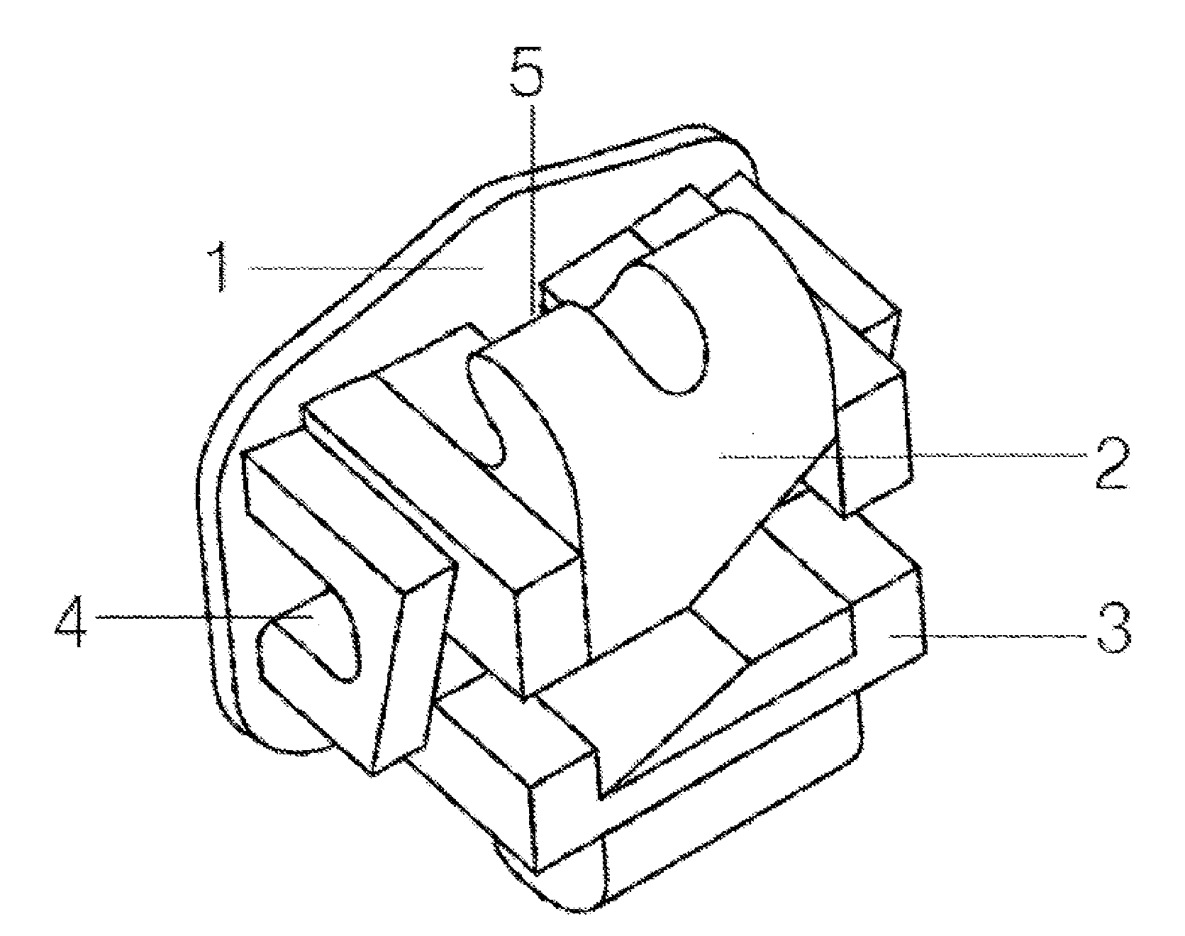
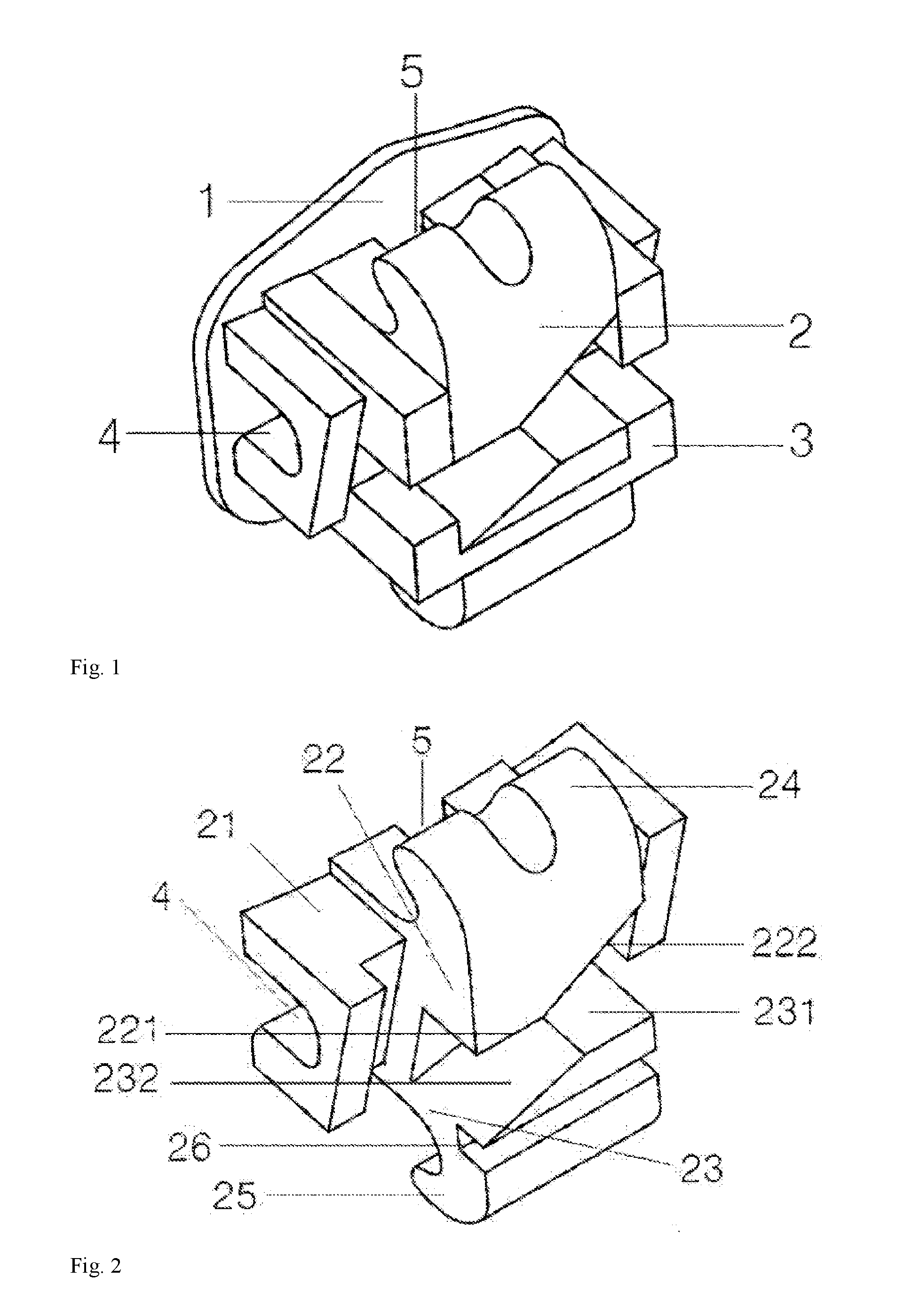
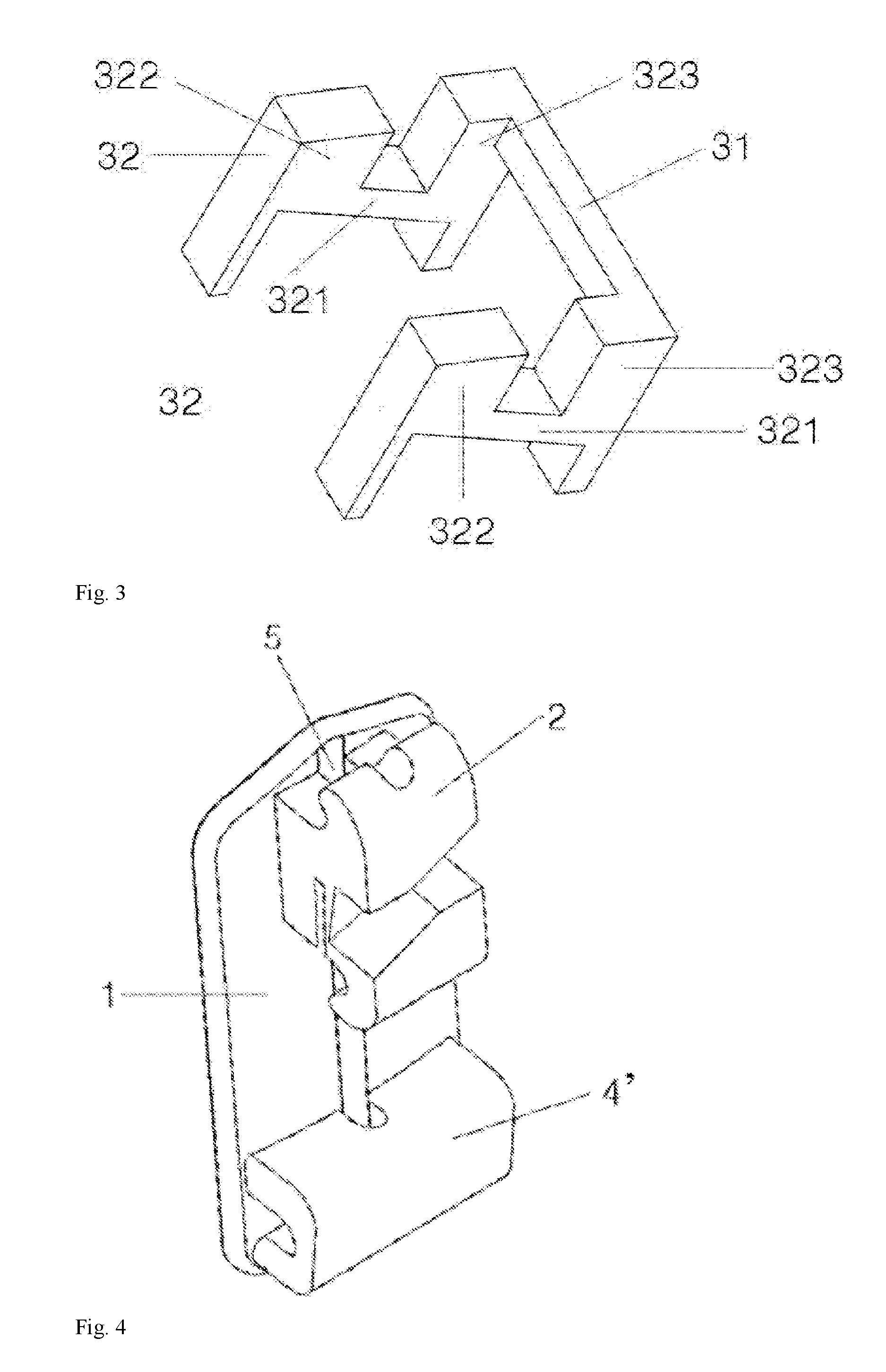
[0057]An orthodontic treatment bracket, as shown in FIG. 1-3, comprising a bracket base 1 and a groove 2, which consists of a groove base 21 secured on the bracket base 1, an upper sidewall 22 and a lower sidewall 23, wherein the said upper sidewall 22 and lower sidewall 23 extend outward to form an upper bracket wing 24 and a lower bracket wing 25 respectively, and the said upper sidewall 22 of said groove consists of an upper lateral sidewall 221 and an upper sloped sidewall 222 which is formed by bend upward at one end thereof, and the said lower sidewall 23 consists of a lower lateral sidewall 231 and a lower sloped sidewall 232 which is formed by bend downward at one end thereof (or, described as the upper sidewall 22 of said mesial groove 2 consists of the upper lateral sidewall 221 and the upper sloped sidewall 222 which is formed by bend upper left at left end thereof, and the lower sidewall 23 of said mesial groove consists of the lower lateral sidewall 231 and the lower sl...

embodiment 2

[0060]This embodiment makes improvement on the structure of auxiliary groove 4 on the basis of Embodiment 1 (see the schematic diagram 8 for the structure of distal auxiliary groove in Embodiment 4). The auxiliary groove 4 is arc-shaped, comprising the upper lateral sidewall 41 and lower lateral sidewall 42 and the top wall 44, wherein the inner surfaces of two lateral sidewalls are wavy folding and relatively protruded, the number of protuberances of the wavy folding and protruded surfaces is 2-8, equally spaced and / or symmetrical, and each folding surface 43′ intersects two by two, forming intersecting lines that are parallel with the upper lateral sidewall 41 and the lower lateral sidewall 42.

embodiment 3

[0061]This embodiment chooses the suitable size on the basis of Embodiments 1 and 2. The diameter of the vertical tube slot 4 is 0.018-0.020 inches, the length of the groove 2 is 0.074-0.145 inches, and the whole groove, after inserting a groove extender 3, is 0.019-0.039 inches longer. The length of the auxiliary groove 4 is 0.137-0.157 inches. See the schematic diagram 9 of the torque angle θ of the mesial groove set forth in Embodiment 5 and the schematic diagram 10 of the axial tilt β, the angle of inclination γ and the included angle α of the bracket. The groove 2 and the auxiliary groove 4 have an axial tilt β, the numerical value of which is adjusted on the basis of the axial tilt value of dental crown; when the bracket is used for mandibular incisor, the β value is the axial tilt value of the tooth plus 2°; when the bracket is used for other teeth, the β value is the axial tilt value of the tooth plus 4°, so as to compensate the “Angle escape”caused by the gap between the ar...


PUM


Abstract

The present invention relates to an orthodontic treatment bracket, which includes a bracket base and a groove with a Tip-edge shape and also has a detachable groove extender. The present invention can switch two different contact modes between the archwire and the bracket groove through flexibly controlling the length of groove with the extender, for purpose of satisfying the different requirements for friction in different clinical treatment stages. The present invention is also related to a double-groove bracket with a groove extender, including a bracket base and a mesial groove and a distal auxiliary groove which are parallel and located at the upper and lower sides of the bracket base. The distance between the base of the mesial groove and the bracket base is greater than the distance between the base of the distal auxiliary groove and the bracket base.

Description

CROSS REFERENCE TO RELATED APPLICATION[0001]This application takes priority from and claims the benefit of Chinese Patent Application No. 201510197038.7 filed on Apr. 23, 2015, the contents of which are herein incorporated by reference.FIELD OF TECHNOLOGY[0002]The present invention belongs to the field of medical device, specifically relating to an orthodontic treatment bracket.BACKGROUND TECHNOLOGY[0003]Malocclusion is a misalignment or incorrect relation between the teeth of two dental arches, and the occlusion disorder and skeletal disharmony of the face is caused thereby. Therefore, two major tasks of orthodontic treatment are: first is position adjustment, namely adjusting the position of teeth so as to correct the malpositioned teeth; second is orientation adjustment, namely adjusting the three-dimensional orientation of teeth, so as to regain normal three-dimensional orientation for abnormally orientated teeth. The purporse of treatment is to achieve normal standard of occlus...

Claims


Application Information

Patent Timeline
Patent Type & Authority Applications(United States)
IPC IPC(8): A61C7/14A61C7/16
CPCA61C7/16A61C7/141A61C7/143
Inventor ZHAO, XILINCHEN, YANGXI
Owner ZHAO XILIN
Why Eureka
Try Eureka