
Modular, blade-rod, intramedullary fixation device

a technology of fixation device and blade rod, which is applied in the field of improved internal fixation means, can solve the problems of orthogonal plane of motion, increased manufacturing cost, and inability to provide stability in all three directions, and achieves the effect of preventing relative movement and enhancing the ability of the blade to stabilize the bon

Active Publication Date: 2009-03-05
CONCEPTS & MEDICINE
View PDF32 Cites 22 Cited by
  • Summary
  • Abstract
  • Description
  • Claims
  • Application Information

AI Technical Summary

Benefits of technology

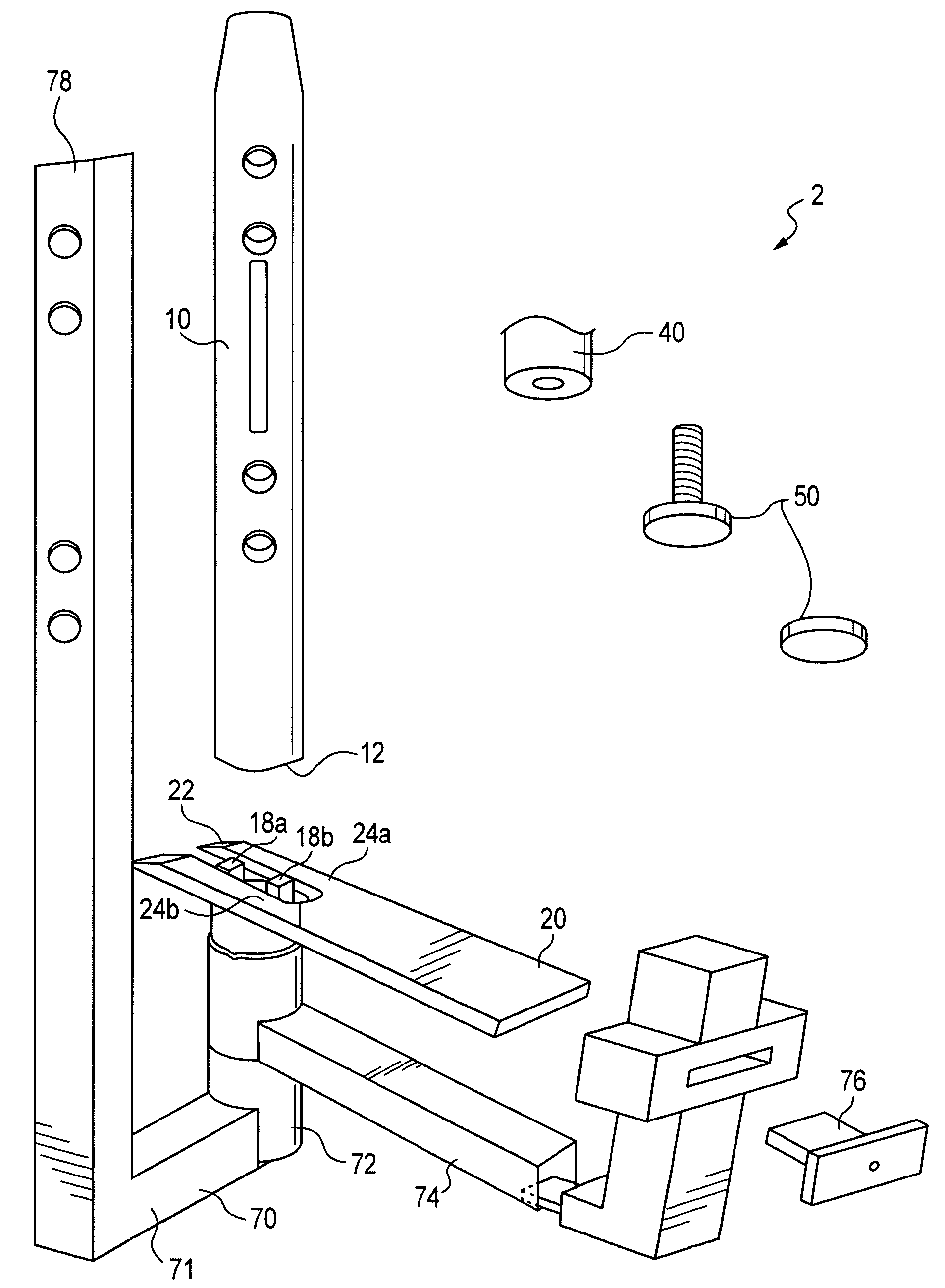
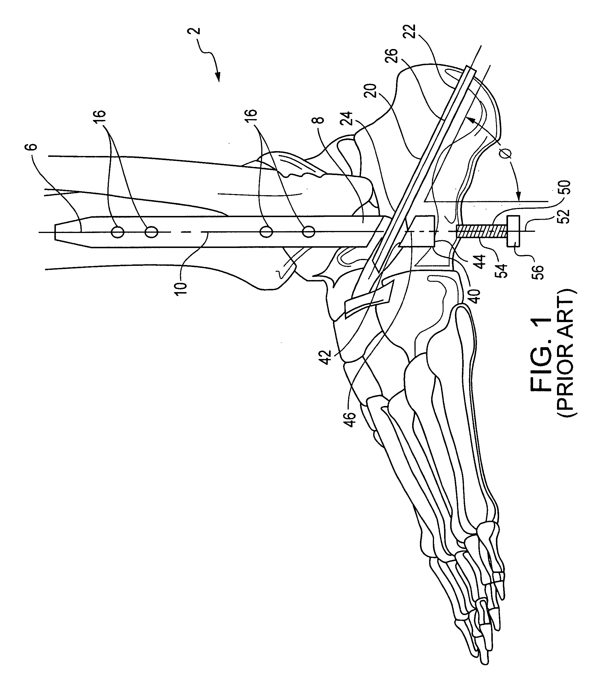
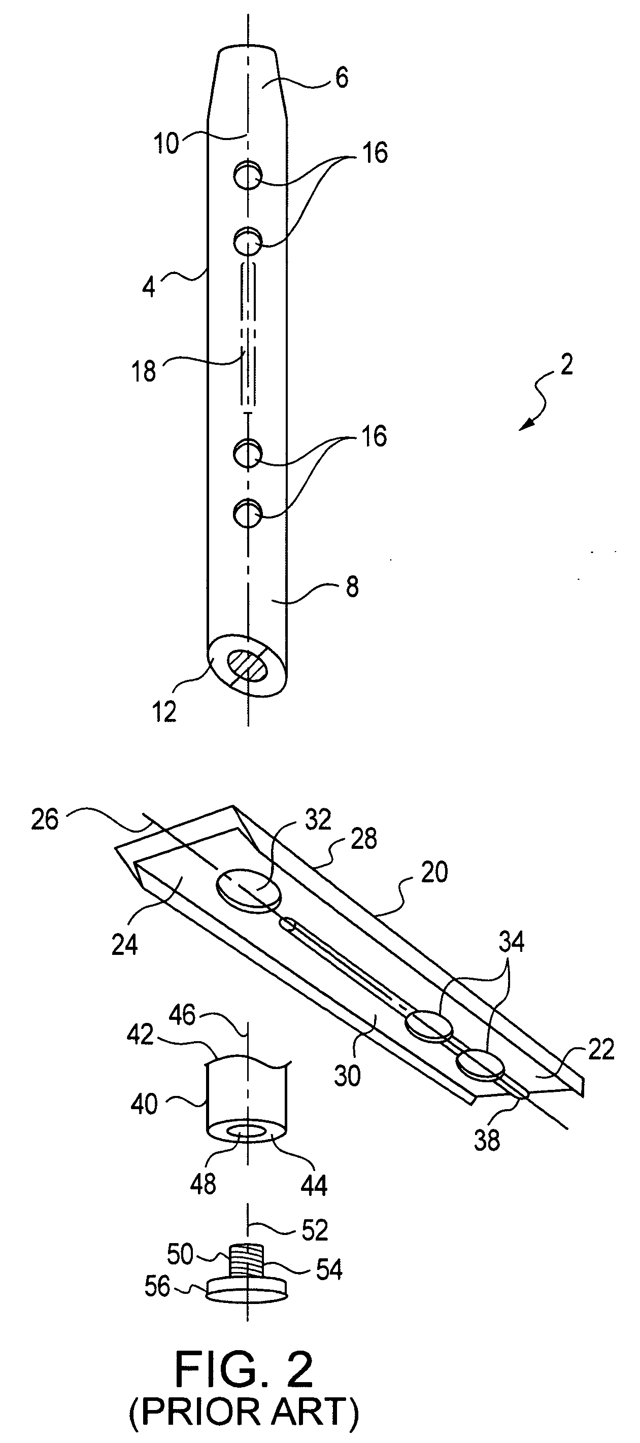
[0026]In accordance with one preferred embodiment of the present invention, the foregoing need can be satisfied by providing an intramedullary fixation device for use in fixing the relative position between a bone having a medullary canal and an adjoining bone or section of bone. Such a device comprises: (1) an intramedullary nail that is to be inserted into the medullary canal of the tubular bone whose position is to be fixed, (2) an elongated blade for insertion into the adjoining bone whose position is to be fixed relative to that of the tubular bone, (3) a coupling element for fixing and locking the relative position of the nail and blade after their insertion, and (4) a means for locating and positioning within the bones to-be-treated the nail and blade. Furthermore, the blade has a cross-sectional shape that is configured in consideration of the geometry of the bone into which the blade is to-be-placed and so as to enhance the ability of the blade to stabilize the bone, and these elements are configured so that they do not have to be decouple during the process of inserting the nail and blade.
[0027]According to a second embodiment of the present invention, a method is provided for stabilizing a specified, relative position between a tubular bone having a medullary canal and an adjoining bone or section of bone. This method comprises the steps of providing the listed elements for the fixation device and then seating the intramedullary nail and blade in the respective tubular and adjoining bones, and utilizing the coupling means so as to lock the elements together and prevent relative movement between the treated bones.

Problems solved by technology

The shape and configuration of such intramedullary nails has been a topic of much inventive effort.
For example, their designs were such that: (1) they often offered only minimal flexibility in addressing situations in which the bones or bone fragments to be stabilized have unique geometries or orientations, (2) they often involved relatively complex designs which tended to increase their costs of manufacture, and (3) their uses were confined primarily to the treatment of fractures and pending fractures in individual large, tubular bones and for limited fusions of the ankle and knee—they had also been used in situations to stabilize one or several bones, but (4) they did not provide stability in all three, orthogonal planes of motion.
For example, it can encounter situations in which the shapes of the bones, whose positions it is meant to stabilize, make insertion of the intramedullary rod and blade exceedingly challenging.
This introduces the potential for instability between the bones and for loss of alignment of the blade relative to the rod, loss of alignment of the rod relative to the foot, and loss of alignment of those bones held by the rod and the blade.
Additional efforts to stabilize the bones without the use of the jig can necessitate other procedural steps that result in increased surgical trauma for the patient.

Method used


Image

  • Modular, blade-rod, intramedullary fixation device
  • Modular, blade-rod, intramedullary fixation device
  • Modular, blade-rod, intramedullary fixation device

Examples


Embodiment Construction

[0040]Before explaining at least one embodiment of the present invention in detail, it is to be understood that the invention is not limited in its application to the details of construction and to the arrangements of the components set forth in the following description or illustrated in the drawings. The invention is capable of other embodiments and of being practiced and carried out in various ways. Also, it is to be understood that the phraseology and terminology employed herein are for the purpose of description and should not be regarded as limiting.

[0041]The present invention is used for the stabilization of fusions and or fractures of bodily bones and joints. To explain this invention, its use has been illustrated within in relation to an ankle surgery.

[0042]To better understand the present invention, it is instructive to consider the procedural steps that are involved in an ankle stabilization surgery which utilizes the previously discussed blade and nail / rod intramedullary...


PUM


Abstract

The intramedullary fixation device for use in fixing the relative position between a tubular bone and an adjoining bone has, according to the present invention, an intramedullary nail that is inserted into the medullary canal of the tubular bone whose position is to be fixed, an elongated blade for insertion into the adjoining bone whose position is to be fixed relative to that of the tubular bone, a coupling element for fixing and locking the relative position of the nail and blade after their insertion, and a means for locating and positioning within the bones to-be-treated the nail and blade. Furthermore, the blade has a cross-sectional shape that is configured in consideration of the geometry of the bone into which the blade is to-be-placed and so as to enhance the ability of the blade to stabilize the bone, and these elements are configured so that they do not have to be decouple during the process of inserting the nail and blade.

Description

CROSS-REFERENCE TO RELATED APPLICATION[0001]This application claims the benefit of Provisional Patent Application No. 60 / 799,222, filed May 10, 2006 by the present inventors. The teachings of this application are incorporated herein by reference to the extent that they do not conflict with the teaching herein.BACKGROUND OF THE INVENTION[0002]1. Field of the Invention[0003]This invention relates to improved internal fixation means used in surgical procedures to treat fractured bones, pending fractures of bones, non-unions, arthritis, as well as any other procedure in which an attempt is made to surgically fuse two or more bones. More particularly, this invention relates to an orthopedic surgical implant and its method of use for stabilizing the relative position between a bone having a medullary canal and an adjoining bone or bone section.[0004]2. Description of the Related Art[0005]In recent years, both solid and tubular, metal rods or intramedullary nails have gradually gained impo...

Claims


Application Information

Patent Timeline
Patent Type & Authority Applications(United States)
IPC IPC(8): A61B17/56A61B17/00
CPCA61B17/1725A61B17/72A61B2017/1775A61B17/725A61B17/7291A61B17/7233A61B17/1775
Inventor PARKS, BRENT G.CHIODO, CHRISTOPHERSCHON, LEW C.
Owner CONCEPTS & MEDICINE
Learn More