Eureka AIR delivers breakthrough ideas for toughest innovation challenges, trusted by R&D personnel around the world.

Clothes treatment apparatus

Inactive Publication Date: 2009-03-12
LG ELECTRONICS INC
View PDF4 Cites 18 Cited by
  • Summary
  • Abstract
  • Description
  • Claims
  • Application Information

AI Technical Summary

Benefits of technology

[0009]An object of the present invention is to provide a clothes treatment apparatus that is capable of reducing noise generated during the operation of the clothes treatment apparatus.
[0011]To achieve these objects and other advantages and in accordance with the purpose of the invention, as embodied and broadly described herein, a clothes treatment apparatus includes a cabinet, a receiving space defined in the cabinet for receiving clothes, air and moisture supply devices for supplying dried air and moisture into the receiving space, respectively, an outfit chamber defined in the cabinet for receiving the hot air and steam supply devices, the outfit chamber including an inlet port for allowing external air to be introduced into the outfit chamber therethrough to cool the hot air and steam supply devices, and a noise prevention device installed at the inlet port for preventing noise generated in the outfit chamber from being discharged out of the outfit chamber through the inlet port.

Problems solved by technology

However, some of the devices installed in the outfit chamber generate high-temperature heat, which may reduce the life spans of the other devices and parts installed in the outfit chamber.
However, the inlet port is open, with the result that noise generated from the various kinds of devices installed in the outfit chamber is discharged out of the outfit chamber through the inlet port.
During the operation of the clothes treatment apparatus, therefore, the clothes treatment apparatus is very noisy, and the various kinds of devices in the outfit chamber of the clothes treatment apparatus may break down due to dust introduced into the outfit chamber.

Method used


Image

  • Clothes treatment apparatus
  • Clothes treatment apparatus
  • Clothes treatment apparatus

Examples


Embodiment Construction

[0023]Reference will now be made in detail to the preferred embodiments of the present invention, examples of which are illustrated in the accompanying drawings. Wherever possible, the same reference numbers will be used throughout the drawings to refer to the same or like parts.

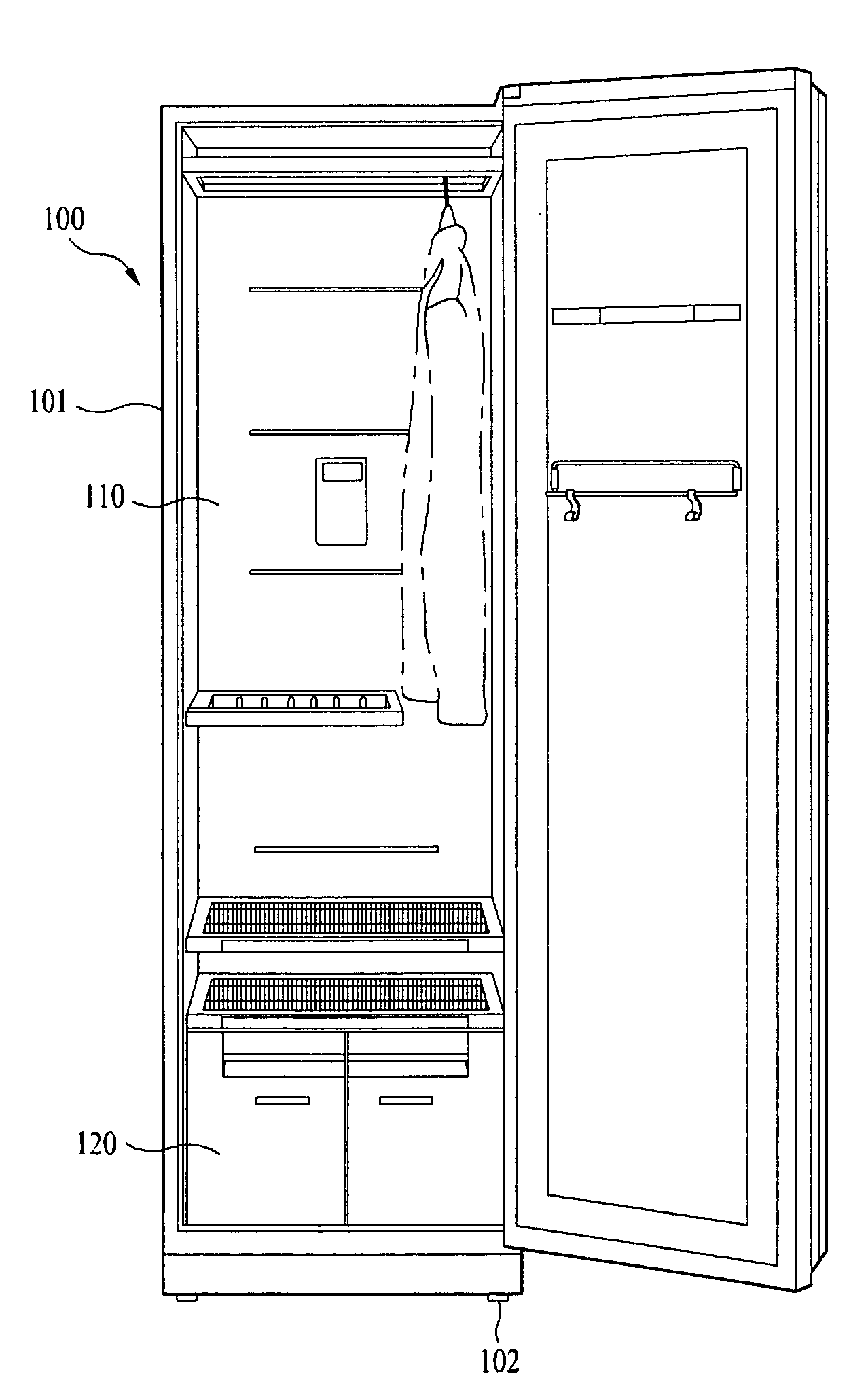
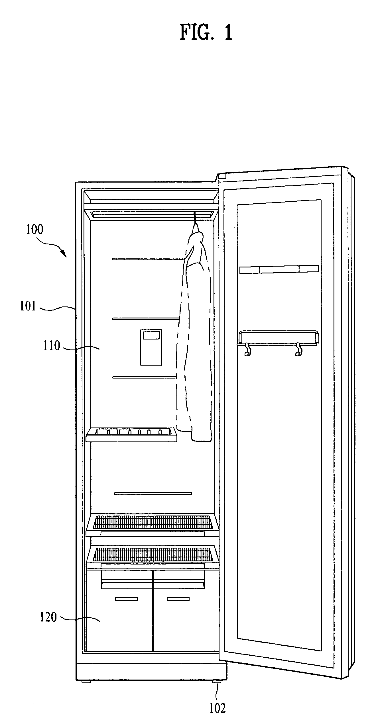
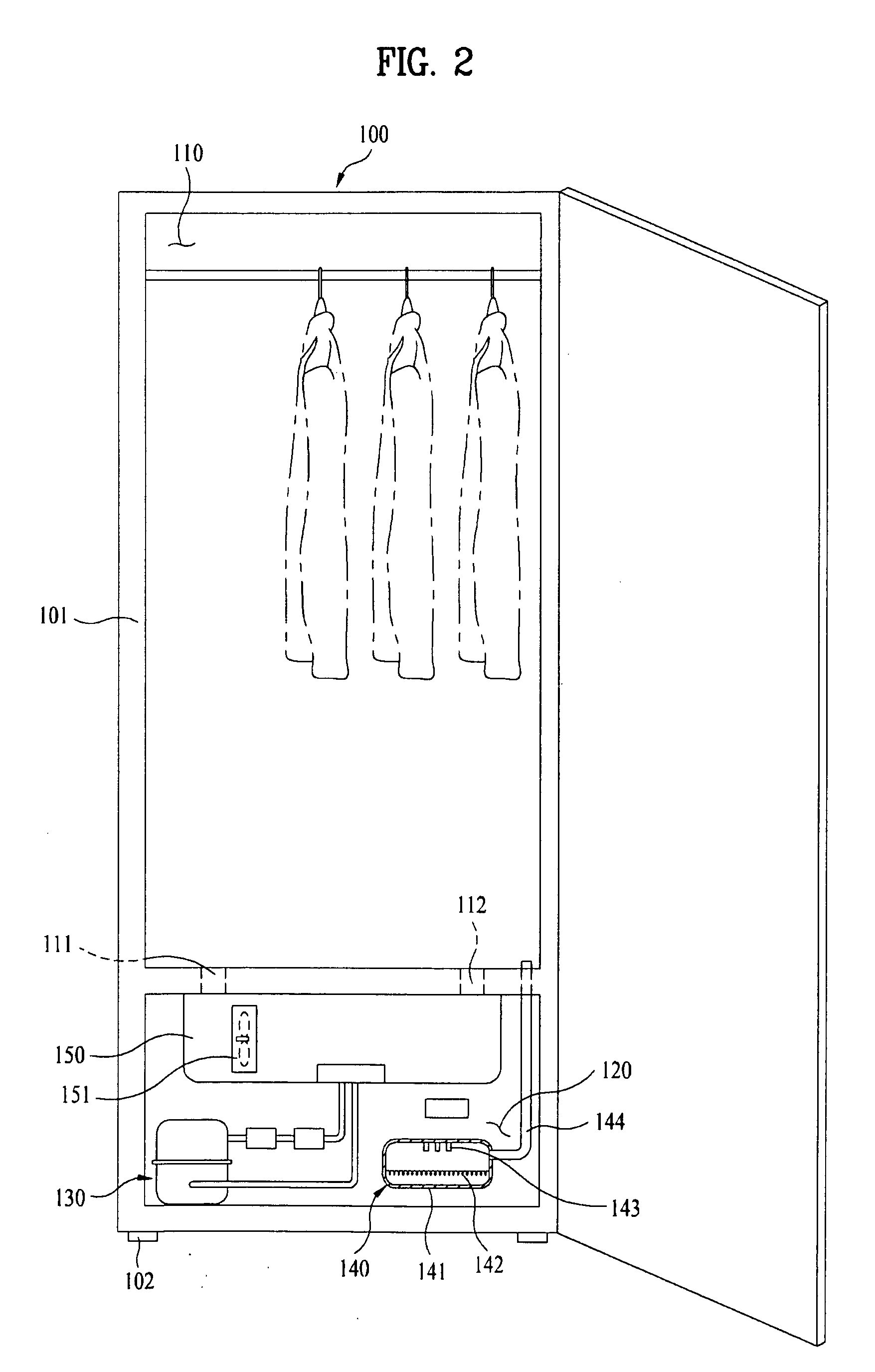
[0024]FIG. 1 is a front view illustrating a clothes treatment apparatus according to the present invention, and FIG. 2 is a front view illustrating the interior of an outfit chamber of the clothes treatment apparatus shown in FIG. 1.

[0025]As shown in FIGS. 1 and 2, a clothes treatment apparatus 100 according to the present invention includes a cabinet 101 basically forming the overall external appearance of the clothes treatment apparatus. In the cabinet 101, at the upper side of the cabinet, a receiving space 110 for receiving clothes is defined. Actually, an inner cabinet is provided at the upper portion in the cabinet 101 of the clothes treatment apparatus, and the receiving space 110 is defined in the in...


PUM


Abstract

A clothes treatment apparatus that treats clothes into a condition suitable to wear is disclosed. The clothes treatment apparatus includes a cabinet, a receiving space defined in the cabinet for receiving clothes, air and moisture supply devices for supplying dried air and moisture into the receiving space, respectively, an outfit chamber defined in the cabinet for receiving the hot air and steam supply devices, the outfit chamber including an inlet port for allowing external air to be introduced into the outfit chamber therethrough to cool the hot air and steam supply devices, and a noise prevention device installed at the inlet port for preventing noise generated in the outfit chamber from being discharged out of the outfit chamber through the inlet port.

Description

CROSS-REFERENCE TO RELATED APPLICATION[0001]This application claims the benefit of Korean Patent Application No. 10-2007-0078171, filed on Aug. 3, 2007, Korean Patent Application No. 10-2008-0022717, filed on Mar. 12, 2008 which is hereby incorporated by reference in its entirety as if fully set forth herein.BACKGROUND OF THE INVENTION[0002]1. Field of the Invention[0003]The present invention relates to a clothes treatment apparatus, and more particularly, to a clothes treatment apparatus that is capable of reducing noise generated from an outfit chamber where various kinds of devices are installed.[0004]1. Discussion of the Related Art[0005]Generally, a clothes treatment apparatus is an apparatus that treats clothes into better conditions. In recent years, there has been popularized a clothes treatment apparatus that is capable of performing various refresh functions, such as removal of wrinkles, smells, and / or static electricity from clothes.[0006]Such a clothes treatment apparatu...

Claims


Application Information

Patent Timeline
IPC IPC(8): F26B25/06G10K11/00
CPCD06F58/203D06F58/10
Inventor MOON, JUNG WOOKPARK, DAE YUNHONG, SOG KIEKIM, JONG SEOKRYU, SEUNG GYULEE, KWANG HEEPARK, HYE YONGCHOI, CHANG GYUKIM, DONG WON
Owner LG ELECTRONICS INC
Why Eureka
Eureka Blog
Learn More