Endotracheal tube with intrinsic suction & endotracheal suction control valve

a technology of intrinsic suction and control valve, which is applied in the field of endotracheal tubes, can solve the problems of affecting the operation, affecting the operation, and presenting a risk to the team personnel, and achieves the effect of minimal effort and minimal disruption of the gas delivery system

a technology of intrinsic suction and control valve, which is applied in the field of endotracheal tubes, can solve the problems of affecting the operation, affecting the operation, and presenting a risk to the team personnel, and achieves the effect of minimal effort and minimal disruption of the gas delivery system

US20090071484A1Inactive Publication Date: 2009-03-19BLACK PAUL WILLIAM +1

Image

  • Endotracheal tube with intrinsic suction & endotracheal suction control valve
  • Endotracheal tube with intrinsic suction & endotracheal suction control valve
  • Endotracheal tube with intrinsic suction & endotracheal suction control valve

Examples


Embodiment Construction

[0020]In describing the preferred and other embodiments of the technology described herein, as illustrated in FIGS. 1-8, specific terminology is employed for the sake of clarity. The invention, however, is not intended to be limited to the specific terminology so selected, and it is to be understood that each specific element includes all technical equivalents that operate in a similar manner to accomplish similar functions.

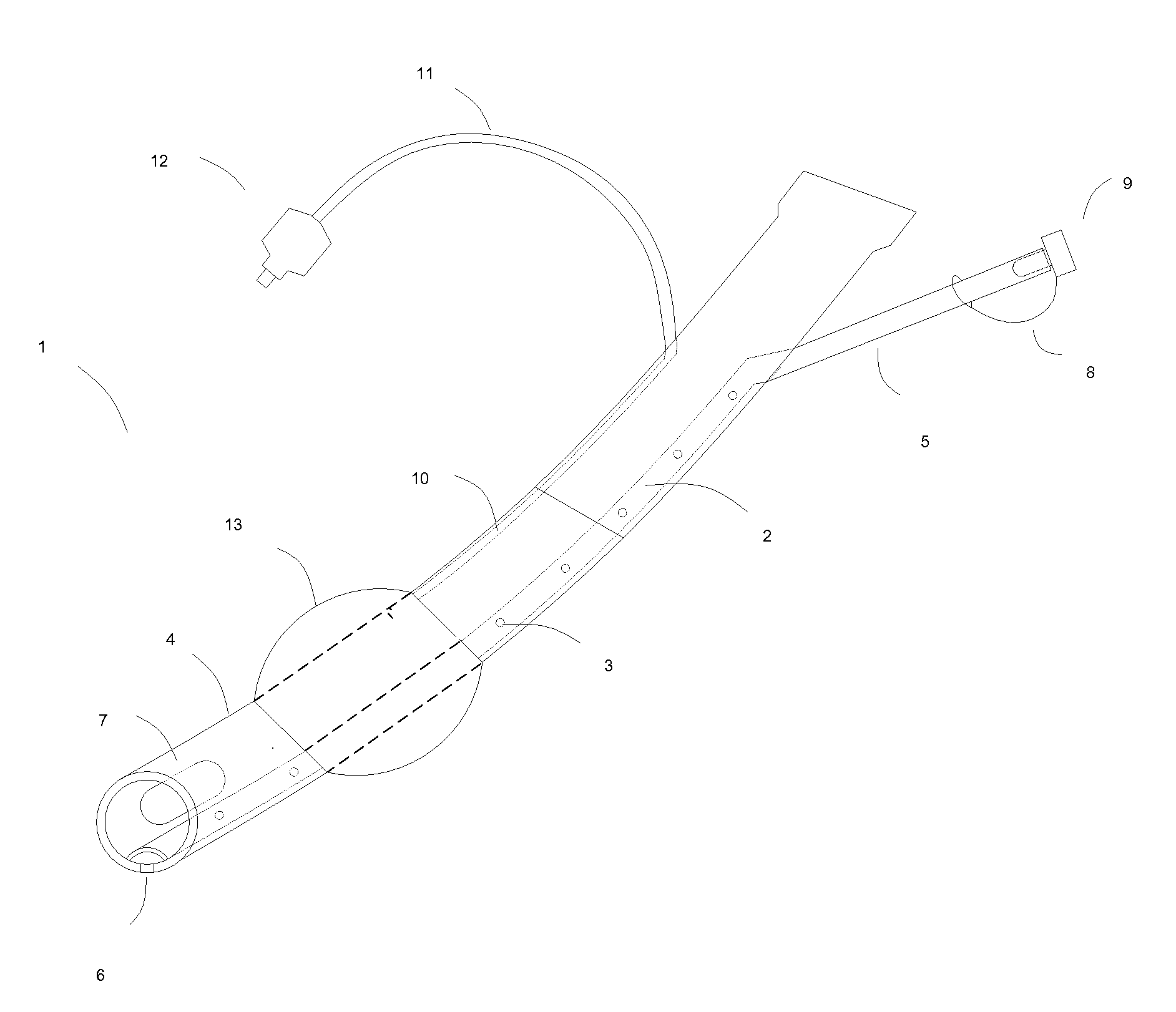
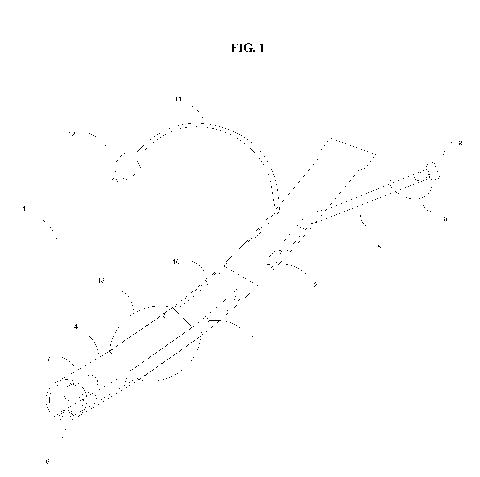
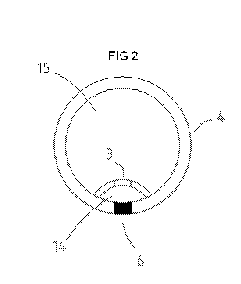
[0021]Referring now to FIG. 1 and FIG. 2, illustrated therein is an embodiment of an improved endotracheal tube with intrinsic suction 1. An outer tube 4 has an outer diameter that approximates the inner diameter of the passage to be intubated. A built in suction channel 2 runs through the outer tube. A plurality of a side hole 3 allows the movement of fluids from the outer tube lumen 15 into the suction channel lumen 14. A suction extension tube 5 is in fluid communication with the suction channel 2 and extends beyond the outer tube 4. An end cap 9 is used to cl...


PUM


Abstract

An improved endotracheal tube providing a built in suction channel for the removal of excessive secretions from the lumen of said tube and the tracheobronchial system is disclosed. Control valves for regulating the suction feature are also disclosed.

Description

BACKGROUND OF THE INVENTION[0001]The technology described herein relates generally to endotracheal tubes used for intubating the trachea and like opening of human and animal bodies.[0002]During general anesthesia the gasses introduced through the endotracheal tube and the tube itself create irritation in the tracheobronchial system resulting in secretions that must be suction removed periodically by the anesthesiologist to clear the airway.[0003]In the current conventional system, this requires detaching the gas delivery apparatus from the end of the endotracheal tube so a smaller suction tube can be introduced and passed down the lumen of the endotracheal tube. When the suctioning is finished, the gas delivery apparatus must be reattached. Thus the flow of essential gasses to the patient is temporarily interrupted and some gasses undesirably escape into the operating room air breathed by the operating team, which can present a risk to the team personnel. Furthermore, the movement o...

Claims


Application Information

Patent Timeline
19 Mar 2009
Publication
US20090071484A1
IPC
A61M16/04
CPC
A61M16/0434; A61M16/0484; A61M16/0463; A61M16/0486
Inventors
BLACK, PAUL WILLIAM; MARTIN, LEILA MEADOWS