
Modular in-line fluid regulators

a fluid regulator and module technology, applied in the direction of fluid pressure control, process and machine control, instruments, etc., can solve the problems of significant changes in the output pressure of the system, significant variation in the regulated output pressure provided by the single-stage regulator, and the regulator system consumes significantly more valuable spa

Inactive Publication Date: 2009-03-19
TESCOM CORP
View PDF10 Cites 43 Cited by
  • Summary
  • Abstract
  • Description
  • Claims
  • Application Information

AI Technical Summary

Benefits of technology

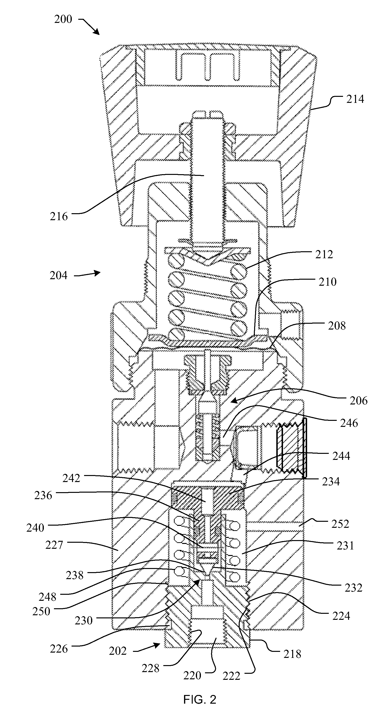
[0006]In accordance with one disclosed example, a fluid regulator apparatus includes a first fluid regulator body having a fluid inlet and a threaded outer surface to engage a threaded opening in a second fluid regulator to serially fluidly couple a first fluid regulator to the second fluid regulator. The fluid regulator apparatus also includes a valve to control a flow of fluid t

Problems solved by technology

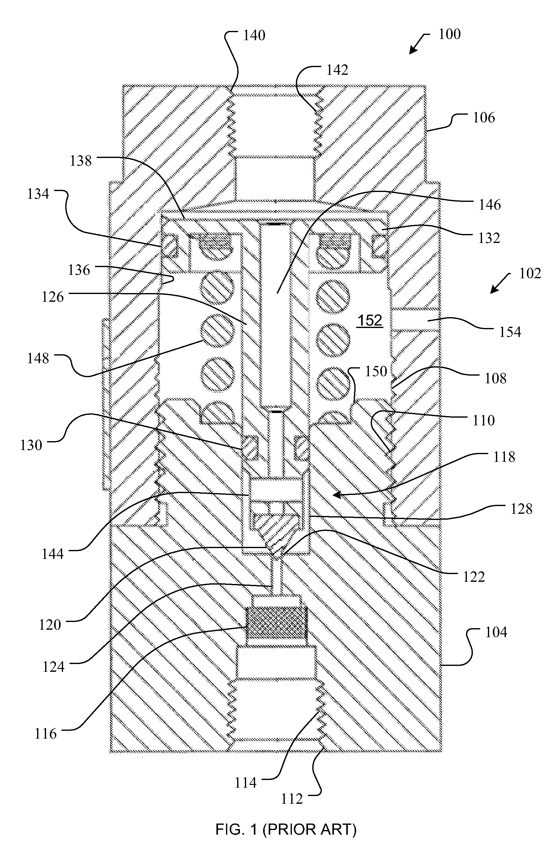
However, such single-stage or one-stage systems may exhibit significant changes in output pressure in response to changes in the inlet or supply pressure.
For example, in some applications, such as those involving regulation of a fluid provided via a high-pressure gas bottle, inlet pressure at the regulator can vary by a factor of six or more, which can cause significant variation in the regulated output pressure provided by a single-stage regulator.
However, in practice, two-stage fluid regulator systems are often implemented after a one-stage system fails to provide a desired level of performance (e.g., a desired maximum output pressure variation).
In either case, such field-based retrofit or re-installation can be very time consuming, costly, and may result in a regulator system that consumes significantly more valuable space (e.g., control cabinet space) in the process control environment.

Method used


Image

  • Modular in-line fluid regulators
  • Modular in-line fluid regulators
  • Modular in-line fluid regulators

Examples


Embodiment Construction

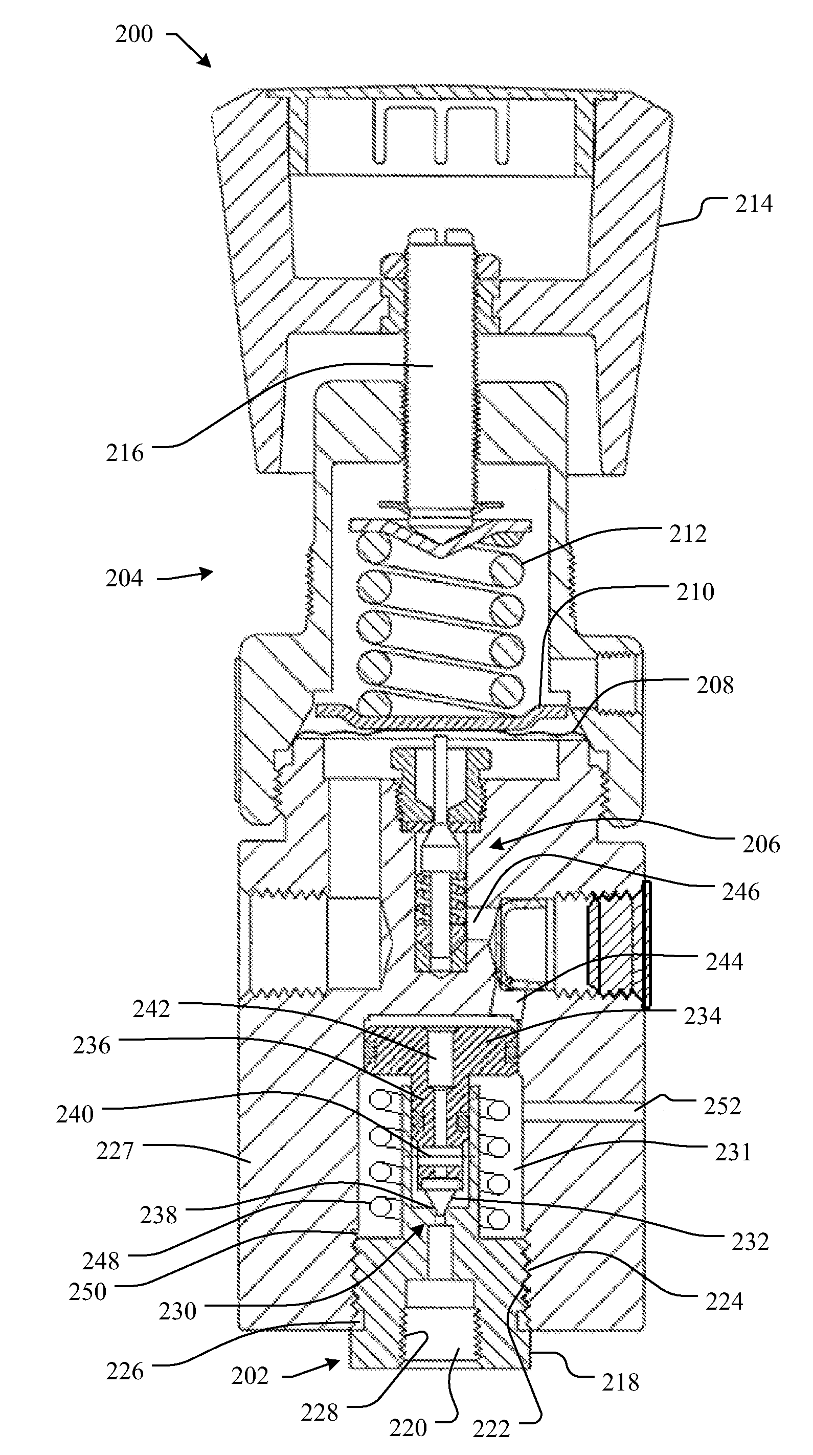
[0013]The example modular in-line fluid regulators described herein can be easily installed in another fluid regulator to form a multi-stage (e.g., two-stage) fluid regulator having excellent regulation characteristics, which minimize the effect of supply or inlet pressure changes on output or outlet pressure. More specifically, in some implementations, the example modular in-line fluid regulators may be installed in the body of another fluid regulator (e.g., a primary adjustable regulator) to form a first stage fluid regulator that is fluidly coupled to the other fluid regulator, which then functions as a second-stage regulator. The other regulator (e.g., the primary adjustable fluid regulator) may include a threaded opening into which the modular in-line fluid regulator is inserted and threadably engaged. Once engaged to the other fluid regulator, the modular in-line fluid regulator may function as a first-stage regulator for the other fluid regulator to enable the other fluid reg...


PUM


Abstract

Modular in-line fluid regulators are described. One described example modular fluid regulator apparatus includes a body having a fluid inlet and a threaded outer surface to engage a threaded opening in another fluid regulator to serially fluidly couple first and second fluid regulators. The example fluid regulator apparatus also includes valve to control a flow of fluid through the first fluid regulator, and a pressure sensing member operatively coupled to the valve to control a position of the valve to provide a regulated output pressure at an outlet of the first fluid regulator. The pressure sensing member and the valve are configured to be received in a cavity of the second fluid regulator adjacent the threaded opening.

Description

FIELD OF THE DISCLOSURE[0001]The present disclosure relates generally to fluid regulators and, more particularly, to modular in-line fluid regulators.BACKGROUND[0002]Process control systems utilize a variety of field devices to control process parameters. Fluid regulators are commonly distributed throughout process control systems to control the pressures of various fluids (e.g., liquids, gasses, etc.). Fluid regulators are typically used to regulate the pressure of a fluid to a substantially constant value. Specifically, a fluid regulator has an inlet that typically receives a supply fluid at a relatively high pressure, which may vary or fluctuate, and provides a relatively lower and substantially constant pressure at an outlet. For example, a gas regulator associated with a piece of equipment may receive a gas having a relatively high pressure from a gas distribution source and may regulate the gas to have a lower, substantially constant pressure suitable for safe, efficient use b...

Claims


Application Information

Patent Timeline
IPC IPC(8): F16K17/00
CPCG05D16/0602G05D16/0663G05D16/103G05D16/02G05D16/0402Y10T137/7784
Inventor PATTERSON, DARYLL DUANEJABLONSKI, JASON DIRK
Owner TESCOM CORP
Learn More