Notched tooth labyrinth seals and methods of manufacture

a technology of labyrinth seals and notched teeth, which is applied in the field of labyrinth seals, can solve problems such as reducing the overall efficiency of engines

Inactive Publication Date: 2009-03-19
HONEYWELL INT INC
View PDF25 Cites 36 Cited by
  • Summary
  • Abstract
  • Description
  • Claims
  • Application Information

AI Technical Summary

Problems solved by technology

In many instances, labyrinth seal leakage may be excessive and may bec

Method used


Image

  • Notched tooth labyrinth seals and methods of manufacture
  • Notched tooth labyrinth seals and methods of manufacture
  • Notched tooth labyrinth seals and methods of manufacture

Examples


Embodiment Construction

[0017]The following detailed description of the inventive subject matter is merely exemplary in nature and is not intended to limit the inventive subject matter or the application and uses of the inventive subject matter. Furthermore, there is no intention to be bound by any theory presented in the preceding background or the following detailed description.

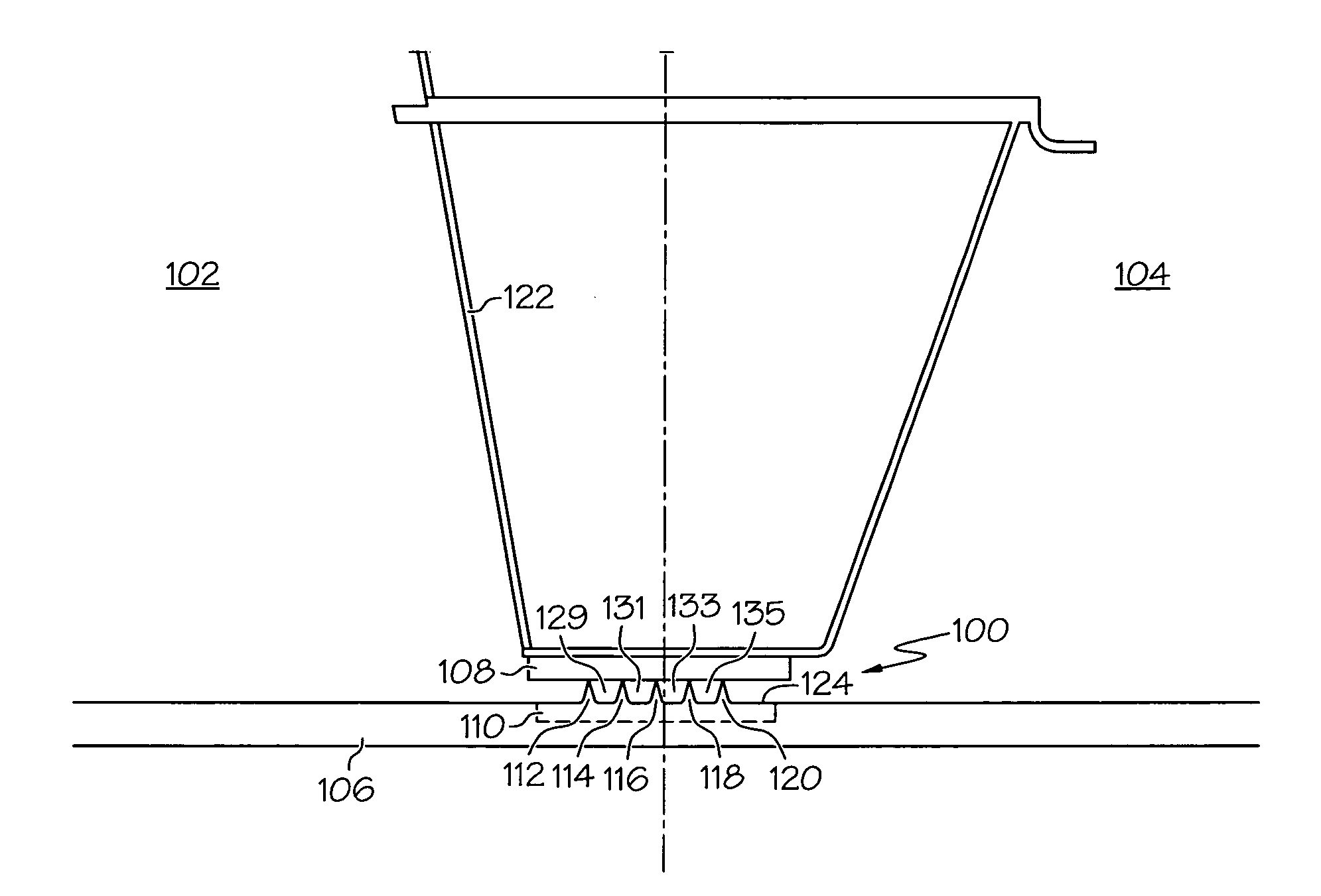
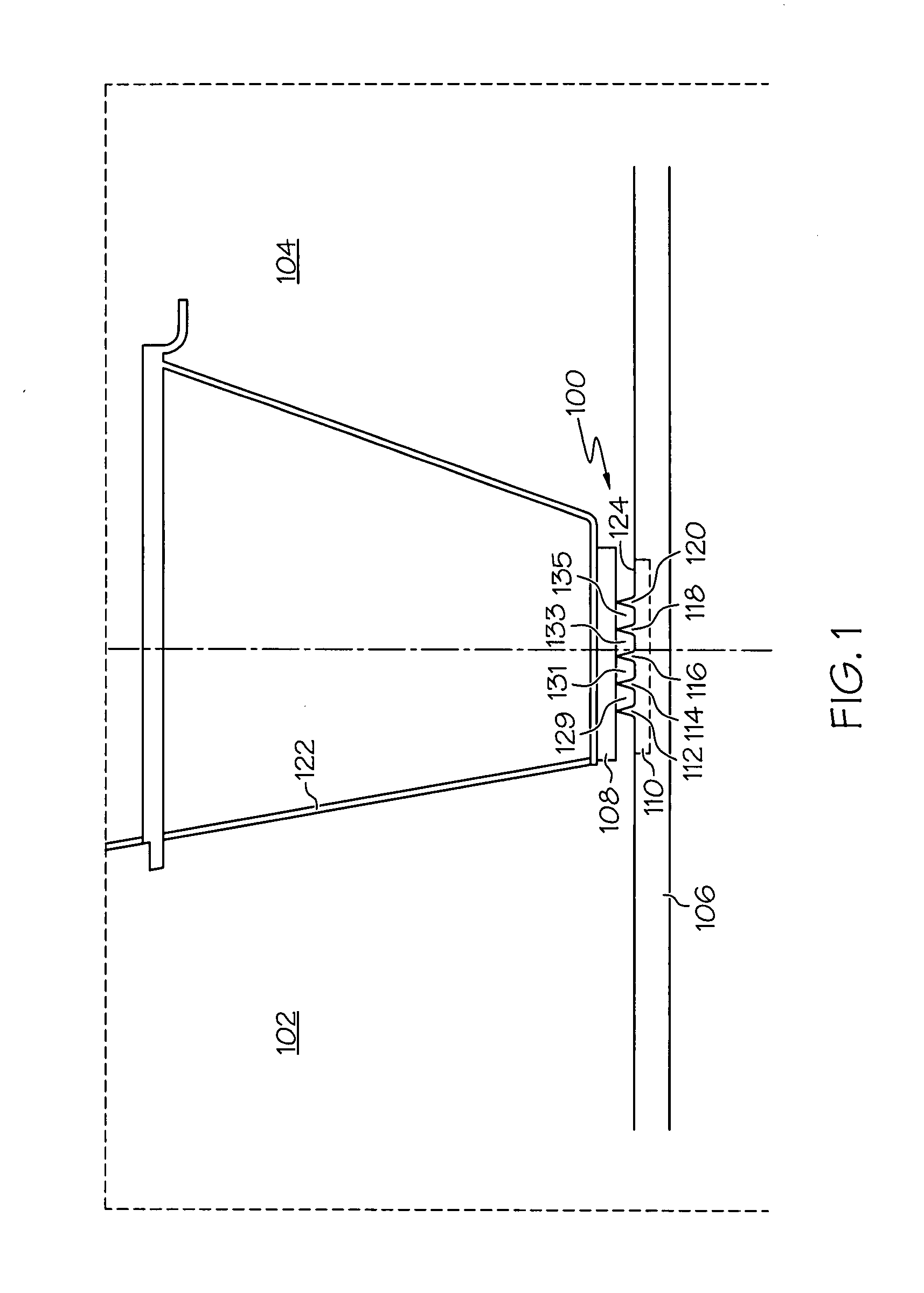
[0018]FIG. 1 is a cross-sectional view of a labyrinth seal 100 disposed between a first cavity 102 and a second cavity 104, according to an embodiment. Although seal 100 is shown in FIG. 1 as being mounted to a shaft 106, it may alternatively be mounted or formed on inserts, rings, couplings, disks, blade tip shrouds or other components. First cavity 102 is a cavity upstream of seal 100, and is also referred to as the higher pressure side of seal 100. Second cavity 104 is downstream of seal 100 and is typically referred to as the lower pressure side. Leakage may occur from first cavity 102 to second cavity 104.

[0019]Labyrinth seal...


PUM

PropertyMeasurementUnit
Fractionaaaaaaaaaa
Fractionaaaaaaaaaa
Fractionaaaaaaaaaa

Abstract

Labyrinth seals and methods of manufacturing the seals are provided. In an embodiment, the seal includes a seal base and a first annular tooth. The seal base has an outer peripheral surface. The first annular tooth extends radially from the seal base outer peripheral surface. The first annular tooth includes a forward wall, an aft wall, and a tip wall, and the forward wall and the aft wall each include bottom sections that contact the seal base and angle upwardly toward or substantially parallel to each other. The forward wall has a notch formed therein defined by a shelf wall and a side wall, the shelf wall and side wall join the forward wall to the tip wall, and the aft wall is formed without a notch. The side wall and the aft wall extend substantially parallel to each other.

Description

TECHNICAL FIELD[0001]The inventive subject matter relates to labyrinth seals and, more particularly, to notched tooth labyrinth seals and methods of manufacturing the seals.BACKGROUND[0002]Turbines provide power for aircraft, ground vehicles, and utilities. Typically, a turbine converts potential energy of a working fluid into mechanical energy and / or propulsive thrust. The working fluid may be a liquid at high pressure, a gas at high pressure such as compressed air, or a gas at high temperature and pressure such as combustion gases, or steam. During turbine operation, a portion of the working fluid flows through a turbine along a main flow path that is defined by stationary and rotating parts that include aerodynamic vanes and blades for extracting power. Another portion of the working fluid may follow a secondary flow path used for cooling to maintain mechanical integrity of turbine components. To maintain efficiency of the turbine, various means of sealing the main and secondary ...

Claims


Application Information

Patent Timeline
IPC IPC(8): F16J15/447B23P17/04F01D11/02
CPCF01D11/001F01D11/02Y10T29/49F16J15/447F16J15/4472F01D11/127
Inventor CHOUGULE, HASHAMRAMERTH, DOUGLAS LYLERAMACHANDRAN, DHINAGARAN
Owner HONEYWELL INT INC
Why Eureka
Try Eureka