
Vehicle air bag minimum distance apparatus, method and system

Inactive Publication Date: 2009-03-19
VEHICLE SAFETY SYST
View PDF31 Cites 2 Cited by
  • Summary
  • Abstract
  • Description
  • Claims
  • Application Information

AI Technical Summary

Benefits of technology

[0011]The present invention is also directed to a method of maintaining a minimum safe clearance between an air-bag mounted in a vehicle and a vehicle passenger including the steps of preventing motion of a seat toward the air-bag beyond a forward-most position wherein, when in the forward-most position, a passenger seated in the seat is separated from the air-bag by a predetermined minimum safe clearance and providing a position adjusting mechanism for at least one vehicle control pedal to allow a passenger seated in the seat to adjust a distance between the seat and the at least one pedal by moving the at least one pedal toward and away from the seat.

Problems solved by technology

Although statistics may indicate that vehicles equipped with air-bags have enhanced passenger safety, under certain conditions air-bags may have been identified as a source of passenger injuries and may have even been cited in some cases as causing death.
As understood, deaths may have been attributed to air-bags predominantly in low-speed accidents, and air-bags may have also been a factor in deaths resulting from high-speed accidents.
Drivers taller than 5′0″ may also position themselves within the minimum safe clearance and this positioning is dangerous regardless of the height of the driver.
In addition to disabling air-bags when the clearance is unsafe, prior systems have slowed the rate of air-bag inflation or inflated the air-bag in stages.
These systems, however, may deprive shorter drivers of the full effectiveness of the air-bag system.
Seat belts, automatic door locks and electric windows often become liabilities following severe impact, rollover, or in submerged vehicle situations.
It is believed, however, that little attention has been paid to computerized safety automation and post-crash escape as they relate to these features.

Method used


Image

  • Vehicle air bag minimum distance apparatus, method and system
  • Vehicle air bag minimum distance apparatus, method and system
  • Vehicle air bag minimum distance apparatus, method and system

Examples


Embodiment Construction

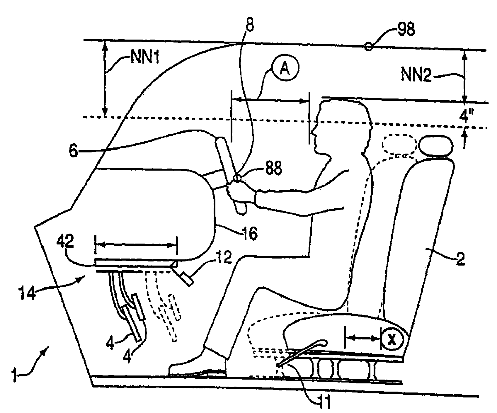
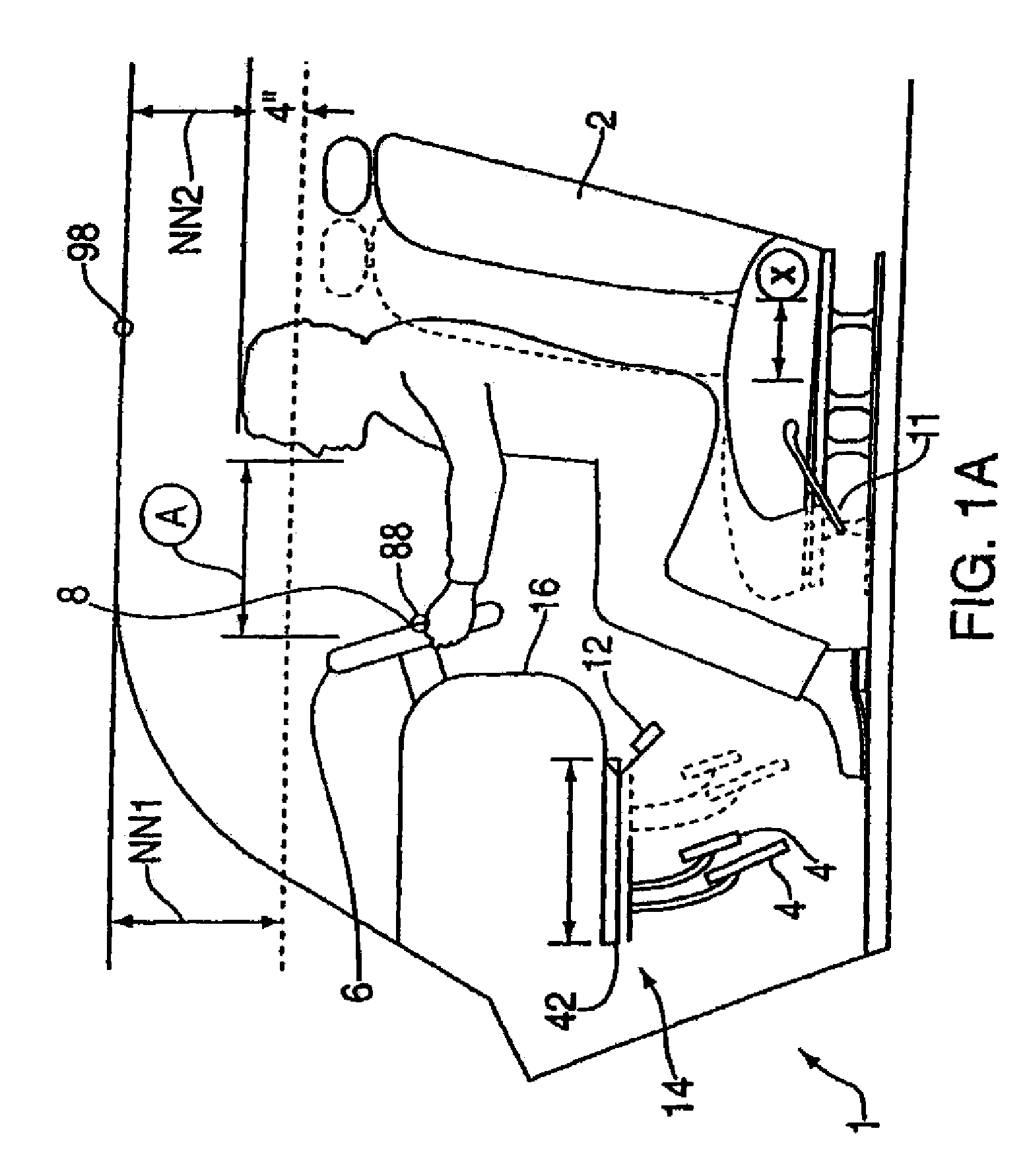
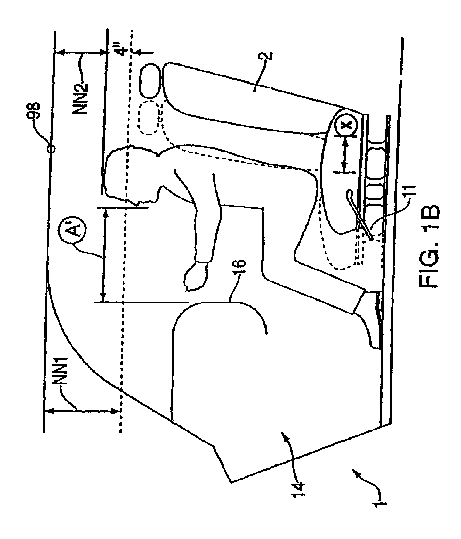
[0022]FIG. 1A shows a system according to an exemplary embodiment of the present invention in which a driver positioned on a seat 2 adjusts the position of the seat 2 to a desired position between rearward and forward-most positions separated by a distance X. Then, the driver adjusts the position of the pedals 4 so that, when in the desired seat position, the driver can comfortably reach the pedals 4 (accelerator, brake, clutch, etc.). Any suitably appropriate manual or automatic seat positioning mechanism may be employed in a vehicle safety device according to the exemplary embodiment and / or exemplary method of the present invention. For example, a seat position adjusting mechanism may include a lever 11 which, in a first position, prevents the seat 2 from moving forward and rearward and which, in a second position, releases the seat 2 so that the seat 2 may be moved forward and rearward by a passenger seated in the seat 2.

[0023]A vehicle safety system according to the exemplary em...


PUM


Abstract

A vehicle safety device includes a seat mounted within a passenger compartment of the vehicle, in which the seat is movably connected to a vehicle frame by a seat position adjusting mechanism that allows the seat to move along an axis between a forward-most position and a rearward-most position. An air-bag is mounted within the passenger compartment in front of the forward-most position of the seat, with the forward-most position of the seat defined as a position of the seat in which a distance between a passenger seated in the seat and the air-bag is equal to a minimum safe clearance. In addition, an exemplary method of maintaining a minimum safe clearance between an air-bag mounted in a vehicle and a vehicle passenger includes the steps of preventing motion of a seat toward the air-bag beyond a forward-most position, in which, when in the forward-most position, a passenger seated in the seat is separated from the air-bag by a predetermined minimum safe clearance, and providing a position adjusting mechanism for at least one vehicle control pedal to allow a passenger seated in the seat to adjust a distance between the seat and the at least one pedal by moving the at least one pedal toward and away from the seat. An automatic seat positioning system, which takes into account both seat to air-bag distance and eye height and automatically, may be used to optimally and automatically position a passenger to maximize safety and comfort.

Description

RELATED APPLICATION INFORMATION[0001]This application is a continuation of U.S. patent application Ser. No. 11 / 490,358, filed Jul. 19, 2006 (allowed), which is a continuation of U.S. patent application Ser. No. 11 / 126,854, filed May 10, 2005, which issued as U.S. Pat. No. 7,092,202 on Aug. 29, 2006, which is a continuation of U.S. patent application Ser. No. 10 / 648,550, filed Aug. 25, 2003, which issued as U.S. Pat. No. 6,916,040 on Jul. 12, 2005, which is a continuation of U.S. patent application Ser. No. 09 / 897,536, filed Jul. 2, 2001, which issued as U.S. Pat. No. 6,634,669 on Oct. 21, 2003, which is a continuation of U.S. patent application Ser. No. 09 / 220,832, filed Dec. 24, 1998, which issued as U.S. Pat. No. 6,293,584 on Sep. 25, 2001, which claims the benefit of and priority to U.S. Provisional Application Ser. Nos. 60 / 101,487, filed Sep. 23, 1998, 60 / 105,245, filed Oct. 22, 1998 and 60 / 105,595, filed Oct. 26, 1998, all of which are incorporated herein by reference.FIELD OF ...

Claims


Application Information

Patent Timeline
IPC IPC(8): B60R21/16B60N2/00B60K23/02B60K26/02B60N2/42B60N2/427B60N2/48B60R21/01B60R21/015G05G1/01
CPCB60K23/02B60K26/02B60N2/002B60N2/4221B60N2/42736B60N2/4279Y10T74/20528B60R2021/0027B60R21/01554B60R21/01512B60R21/0153Y10T74/2054Y10T74/20534B60N2/4885B60N2/888
Inventor LEVINE, RICHARD M.
Owner VEHICLE SAFETY SYST
Learn More