This helps you quickly interpret patents by identifying the three key elements:
Problems solved by technology
Method used
Benefits of technology
Benefits of technology
[0011]Embodiments also provide a spindle motor capable of reducing rotational eccentricity in a radial direction of a rotation shaft.
[0012]Embodiments further provide a spindle motor capable of reducing surface vibration in an axial direction of a disk.
Problems solved by technology
Thus, in a related art spindle motor, the surface vibration in an axial direction of a disk mounted on the rotor that is coupled to the rotation shaft 15, or the upward and downward surface vibration, becomes severe and reduces product reliability.
In particular, when the disk is rotated at low speeds, the surface vibration in the axial direction of the disk increases, so that when a predetermined design is printed on the surface of the disk, lines to be represented overlap or are not accurately represented.
Method used
Image
Click on the blue label to locate the original text in one second.
Reading with bidirectional positioning of images and text.
Examples
first embodiment
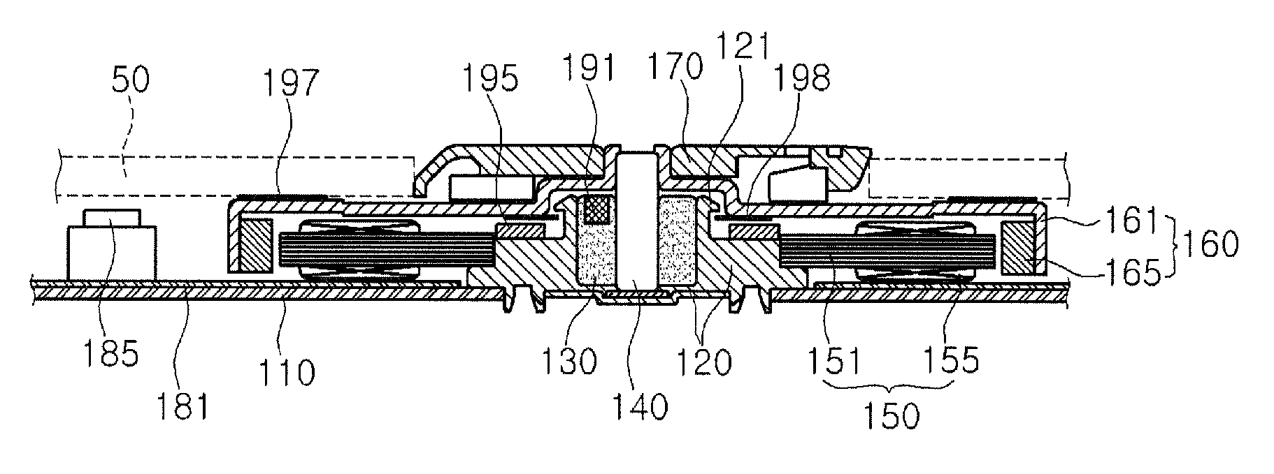
[0031]In a spindle motor according to the present invention, orbiting of the rotation shaft 140 is prevented to reduce the surface vibration in a radial direction of the rotation shaft 140.
[0032]The bearing 130 has a first suction magnet 191 formed thereon to attract the rotation shaft 140 with biased pulling force of the first suction magnet 191.
[0033]Referring to FIG. 2, the first suction magnet 191 is formed integrally with an inner side of the bearing 130 to draw the rotation shaft 140 toward a side of the bearing 130.
[0034]For example, the first suction magnet 191 may be formed within the bearing 130, or may be formed atop the bearing 130. The first suction magnet 191 may be formed such that at least a portion is inserted in the bearing 130.
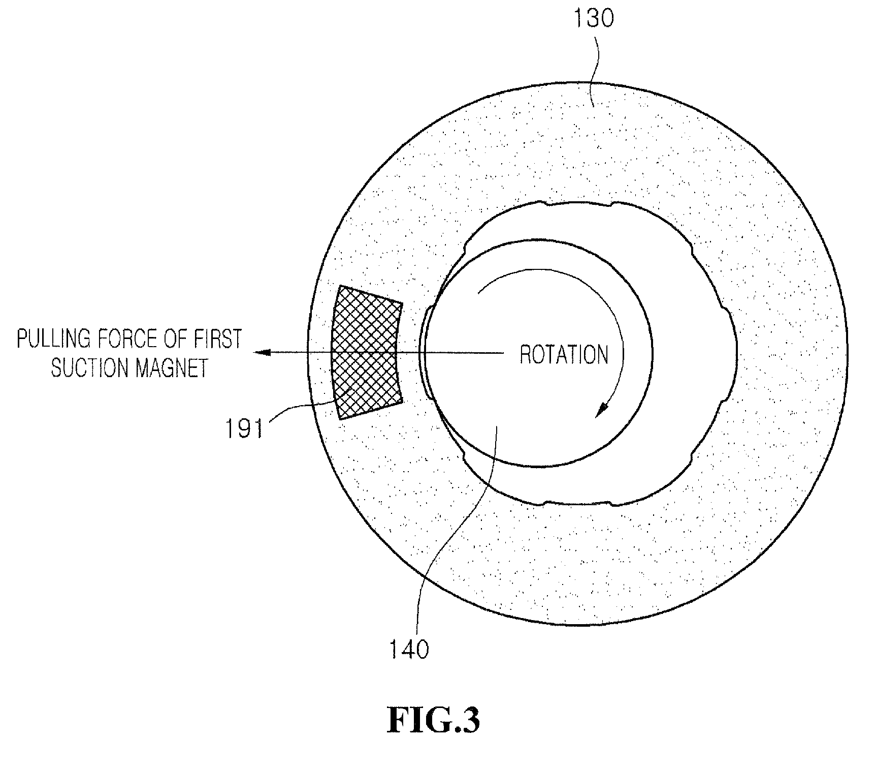
[0035]When the bearing 130 is viewed from the side, the first suction magnet 191 may be formed to project upward and be disposed eccentrically from the vertical center of the bearing 130.
[0036]Accordingly, as shown in FIG. 3, the first sucti...
second embodiment
[0042]FIG. 4 is a plan view of a spindle motor according to the present invention, and descriptions already given with reference to FIG. 2 will not be provided again.
[0043]Referring to FIG. 4, a second suction magnet 291 is integrally formed on one side within the bearing 130 to draw the rotation shaft 140 toward one side of the bearing 130.
[0044]The second suction magnet 291 may be formed at the lower portion of the bearing 130. The second suction magnet 291 may be formed such that at least a portion thereof is inserted into the bearing 130.
[0045]When the bearing 130 is viewed from the side, the second suction magnet 291 may be formed to be disposed biased downward from the vertical center of the bearing 130.
[0046]FIG. 5 is a plan view of a spindle motor according to a third embodiment of the present invention, and FIG. 6 is a plan view of a spindle motor according to the third embodiment of the present invention.
[0047]Referring to FIGS. 5 and 6, the first suction magnet 191 and th...
PUM
Abstract
A spindle motor is provided. The spindle motor includes a base, a bearing housing, a bearing, a rotation shaft, a stator, and a rotor. The bearing housing is installed on the base. The bearing is press-fitted in the bearing housing, and includes a suction magnet installed therein. The rotation shaft is rotatably supported by the bearing, and is drawn by the suction magnet. The stator is supported by the base. The rotor is coupled to the rotation shaft to be rotated through interaction with the stator.
Description
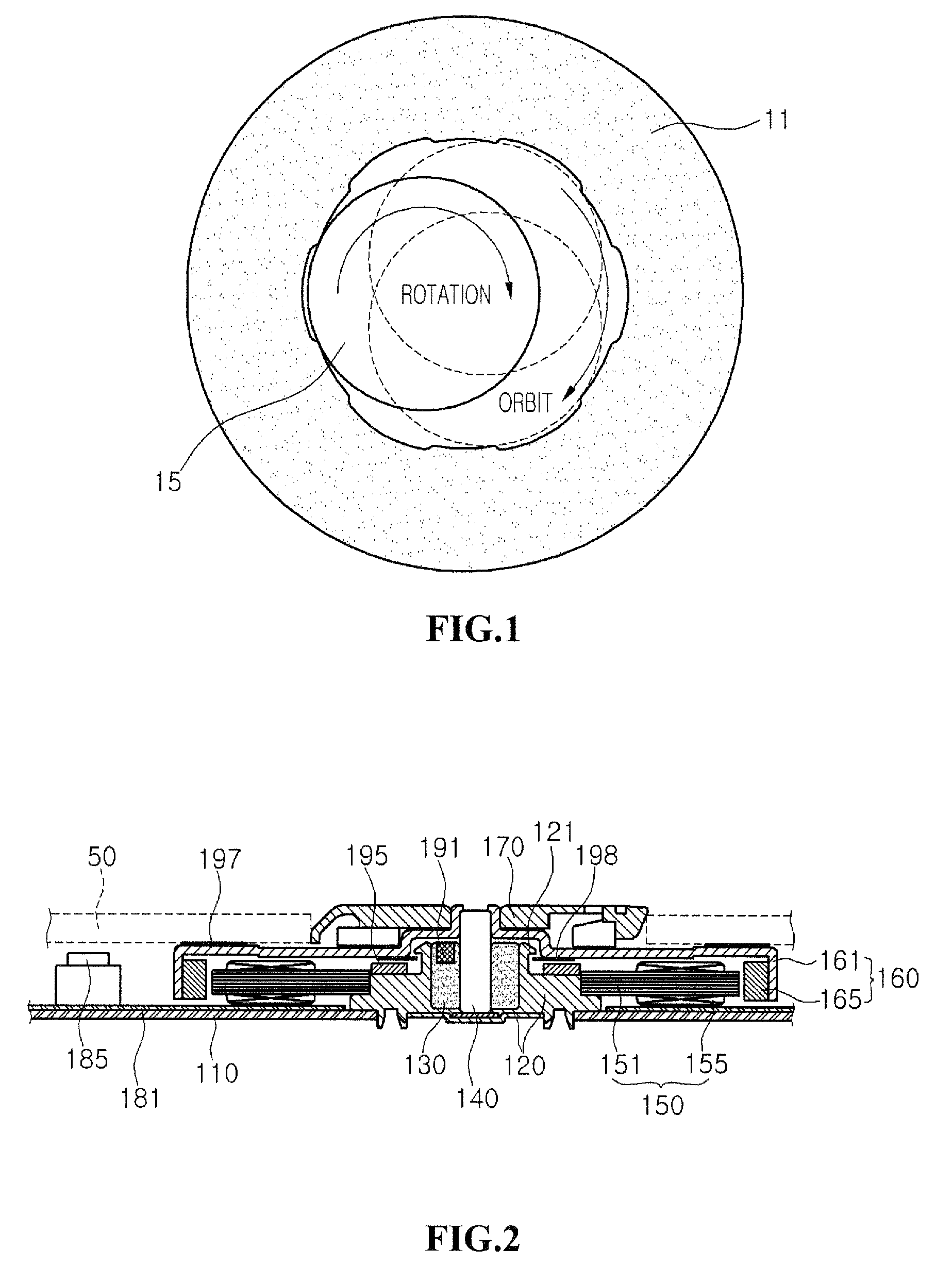
CROSS-REFERENCE TO RELATED APPLICATION[0001]The present application claims the benefit under 35 U.S.C. § 119 of Korean Patent Application No. 10-2007-0094716, filed Sep. 18, 2007, which is hereby incorporated by reference in its entirety.BACKGROUND[0002]The present embodiments relate to a spindle motor.[0003]A spindle motor is installed inside an optical disk drive (ODD), and performs the function of rotating a disk to enable an optical pickup to read data recorded on the disk.[0004]FIG. 1 is a plan view showing a rotation shaft supported on a bearing in a spindle motor according to the related art.[0005]Referring to FIG. 1, a rotation shaft 15 is installed to be supported and capable of rotating in a bearing 11 press-fitted and fixed in a bearing housing (not shown).[0006]The rotation shaft 15 is coupled to a rotor (not shown), and the rotor is rotated (together with the rotation shaft 15) through interaction between a stator (not shown) and the rotor. Here, the rotation shaft 15 s...
Claims
Application Information
Patent Timeline
Application Date:The date an application was filed.
Publication Date:The date a patent or application was officially published.
First Publication Date:The earliest publication date of a patent with the same application number.
Issue Date:Publication date of the patent grant document.
PCT Entry Date:The Entry date of PCT National Phase.
Estimated Expiry Date:The statutory expiry date of a patent right according to the Patent Law, and it is the longest term of protection that the patent right can achieve without the termination of the patent right due to other reasons(Term extension factor has been taken into account ).
Invalid Date:Actual expiry date is based on effective date or publication date of legal transaction data of invalid patent.

