
Adjustable Anti-roll bar for vehicles

a technology for anti-roll bars and vehicles, applied in the direction of resilient suspensions, vehicle springs, interconnection systems, etc., can solve the problems of reducing cornering traction, increasing the cost of maintaining maximum road surface tire contact, and increasing body roll

Active Publication Date: 2009-03-26
DRINAN DANNY J
View PDF4 Cites 13 Cited by
  • Summary
  • Abstract
  • Description
  • Claims
  • Application Information

AI Technical Summary

Problems solved by technology

The presence of the torsion bars in the suspension, however, also allow the vehicle to roll from side to side under cornering, which has many undesirable consequences for vehicle handling, such as reduced cornering traction caused by the changing suspension geometry no longer keeping the bottom of the tire parallel with the road surface.
The use of stiffer torsion bars will reduce the amount of body roll, but at the expense of maintaining maximum road surface tire contact.
Therefore, too stiff of an anti-roll bar can actually cause the inside tire to lift off of the ground, which is obviously an undesirable result.
Increasing the traction of the outside wheel on one end of the car may leave the other end of the car with too little traction to match the performance of the first end.
With such an imbalance of traction, one end of the car will lose traction before the other end.
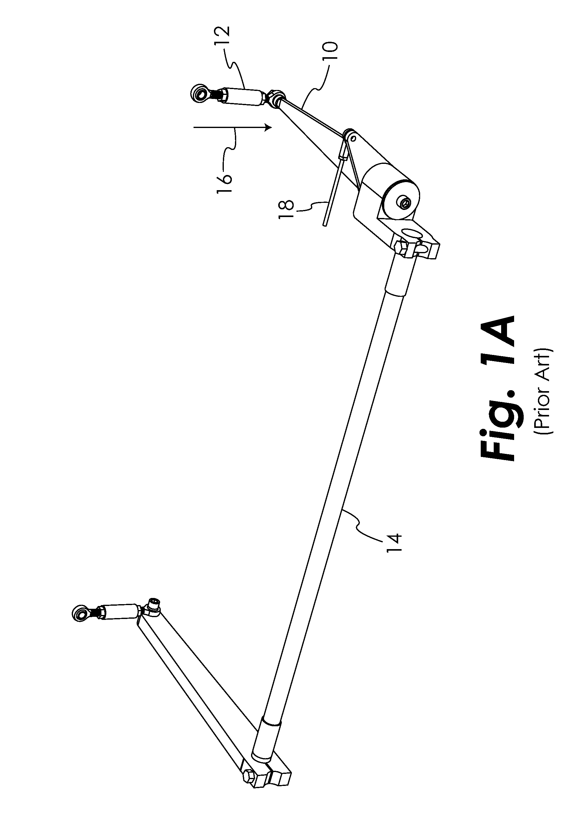
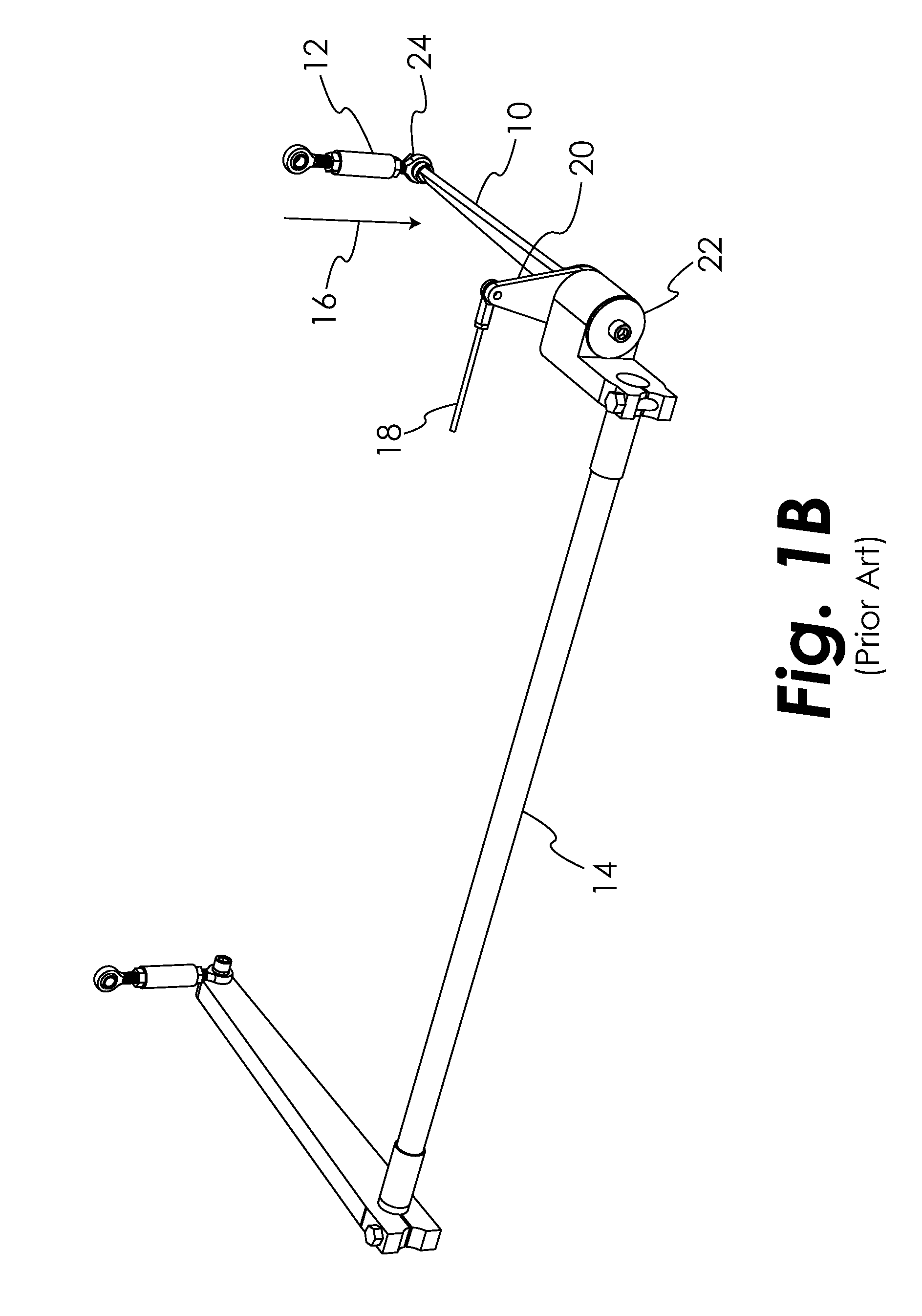
Although the anti-roll bar of FIGS. 1A-C is adjustable, the range of adjustability is fairly limited.

Method used


Image

  • Adjustable Anti-roll bar for vehicles
  • Adjustable Anti-roll bar for vehicles
  • Adjustable Anti-roll bar for vehicles

Examples


Embodiment Construction

[0019]For the purpose of promoting an understanding of the principles of the disclosure, reference will now be made to the embodiments illustrated in the drawings and specific language will be used to describe the same. It will nevertheless be understood that no limitation of the scope of the claims is thereby intended, such alterations and further modifications in the illustrated device, and such further applications of the principles of the disclosure as illustrated therein, being contemplated as would normally occur to one skilled in the art to which the disclosure relates.

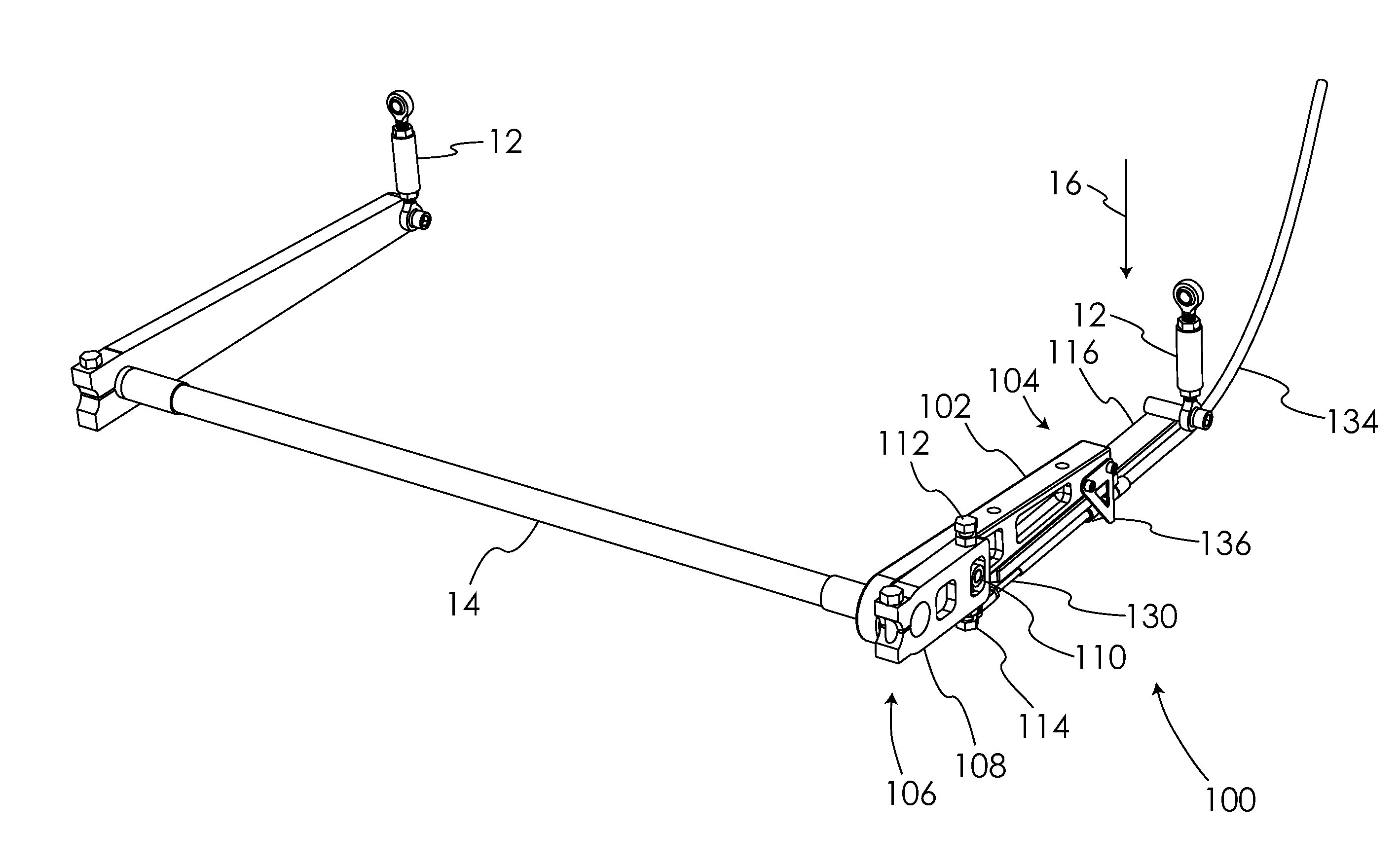
[0020]The presently disclosed embodiments describe an anti-roll bar system that allows for real-time adjustment of the spring rate from the vehicle cockpit. This allows the driver to adjust the anti-roll spring rate dynamically in order to adjust for changing driving conditions, such as tire wear through the course of a race.

[0021]Referring to FIGS. 2 and 3, there is illustrated a first embodiment anti-roll bar...


PUM


Abstract

An adjustable anti-roll bar for a vehicle having a suspension that is moveable with respect to the vehicle chassis is disclosed, the adjustable anti-roll bar including a flexible member having a flexible member first side, a flexible member second side, a flexible member proximal end adapted to be coupled to said suspension and a flexible member distal end; a frame operably positioned on said flexible member first side; a sliding member operably positioned on said flexible member second side, said sliding member having a sliding member proximal end and a sliding member distal end, said sliding member proximal end defining a first fulcrum about which said flexible member will bend when said suspension applies force in a first direction to said flexible member proximal end; and an actuating member operably coupled to said sliding member, said actuating member operable to cause said sliding member to move with respect to said flexible member, whereby a position of said first fulcrum with respect to said flexible member moves and a spring rate of said adjustable anti-roll bar changes.

Description

TECHNICAL FIELD OF THE INVENTION[0001]The present invention generally relates to vehicle suspension systems and, more particularly, to adjustable anti-roll bars for vehicles.BACKGROUND OF THE INVENTION[0002]Anti-roll bars are used in sprung vehicle suspensions in order to reduce body roll during cornering by adding to the roll resistance of the suspension components such as springs and torsion bars. Springs and torsion bars (referred to hereinafter collectively as “torsion bars”) in a vehicle suspension are provided to allow the wheels to maintain maximum contact with the road surface when the vehicle travels over imperfections in the roadway. The presence of the torsion bars in the suspension, however, also allow the vehicle to roll from side to side under cornering, which has many undesirable consequences for vehicle handling, such as reduced cornering traction caused by the changing suspension geometry no longer keeping the bottom of the tire parallel with the road surface. This ...

Claims


Application Information

Patent Timeline
IPC IPC(8): B60R21/13
CPCB60G2202/135B60G21/0553
Inventor DRINAN, DANNY J.
Owner DRINAN DANNY J
Learn More