Image Forming Device

a technology of forming device and image, which is applied in the direction of instruments, electrographic process equipment, optics, etc., can solve the problems of dust tainted or damaged surfaces of exposed surfaces

Active Publication Date: 2009-04-02
BROTHER KOGYO KK
View PDF3 Cites 17 Cited by
  • Summary
  • Abstract
  • Description
  • Claims
  • Application Information

AI Technical Summary

Benefits of technology

[0010]Aspects of the present invention is advantageous to provide one or more improved image forming devices that can prevent

Problems solved by technology

Thereby, the exposure surfaces might be da

Method used


Image

  • Image Forming Device
  • Image Forming Device
  • Image Forming Device

Examples


Embodiment Construction

[0026]It is noted that various connections are set forth between elements in the following description. It is noted that these connections in general and, unless specified otherwise, may be direct or indirect and that this specification is not intended to be limiting in this respect.

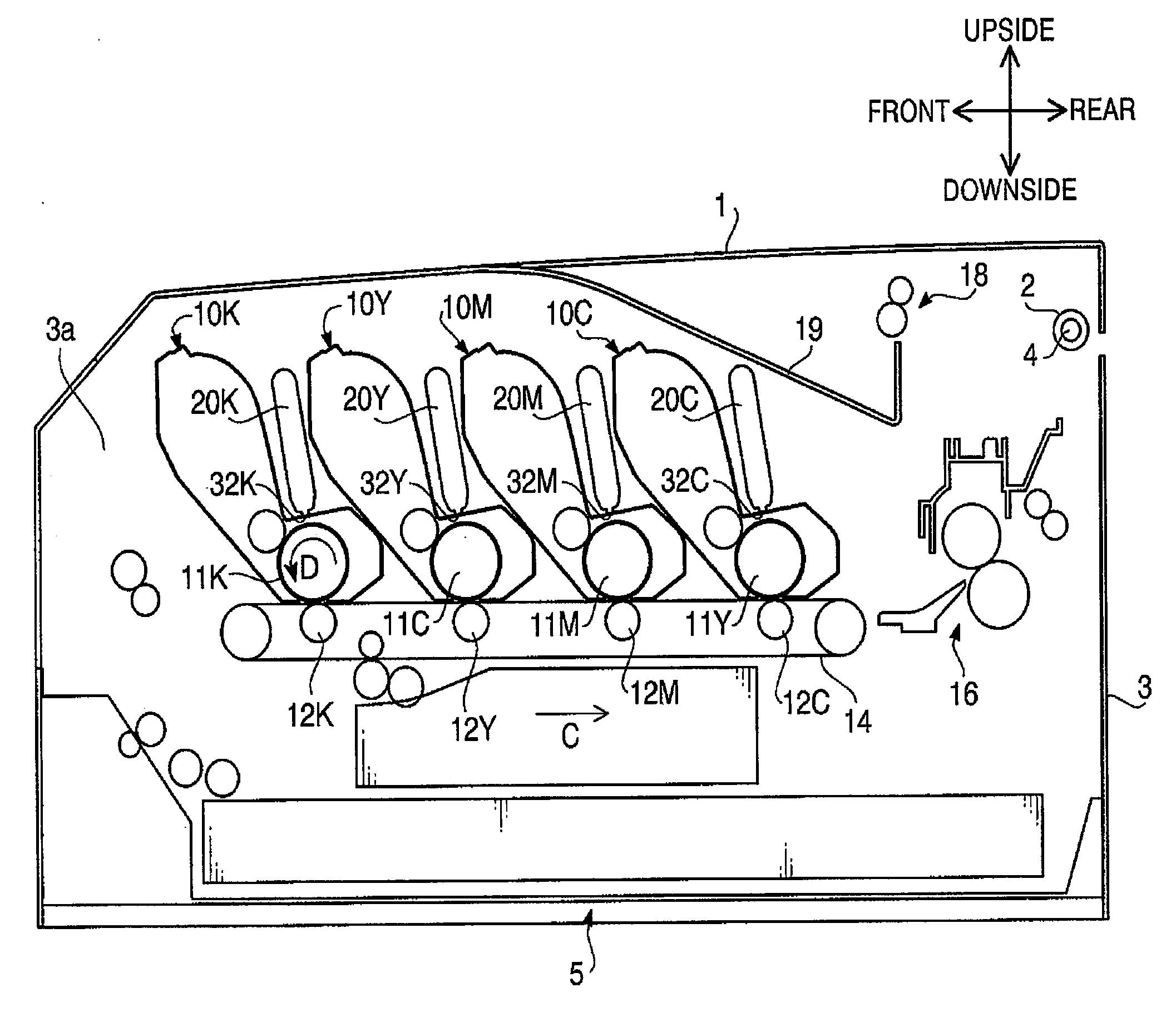
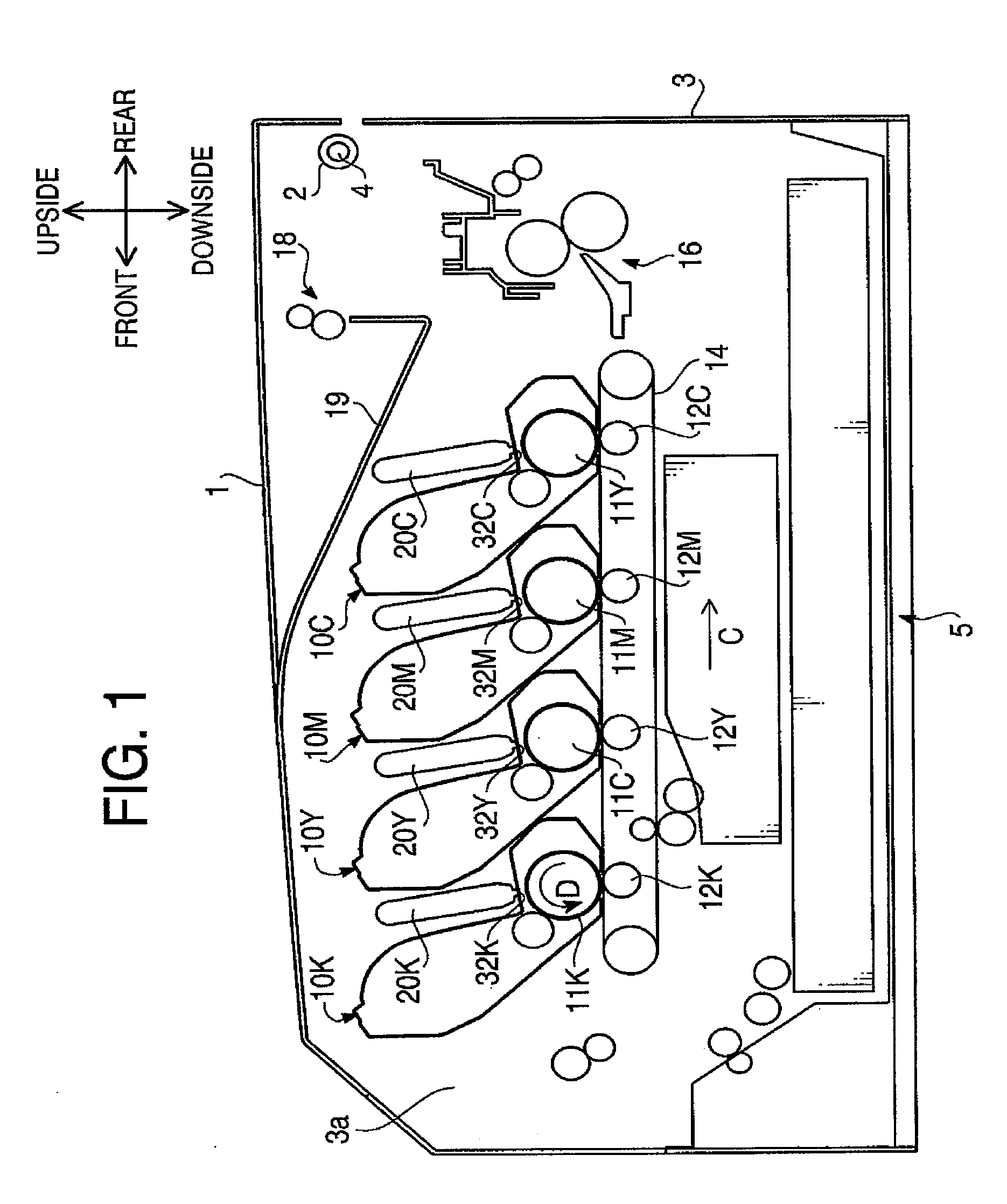
[0027]Hereinafter, an embodiment according to aspects of the present invention will be described with reference to the accompany drawings. FIG. 1 is a cross-sectional view schematically showing an entire configuration of an LED printer 5 in an embodiment according to aspects of the present invention. In the LED printer 5 shown in FIG. 1, a left side, a right side, a back side, and a front side on the figure are defined as a front side, a rear side, a left side, and a right side, respectively.

[0028]In FIG. 1, an upper case 1 is supported, rotatably with respect to a mechanical unit 3, by a rotational shaft hole 2 provided at a rear side of the upper case 1 and a rotational shaft 4 provided at a rear side ...


PUM


Abstract

An image forming device includes a first device body, a second device body having a first side end and a second side end opposite to the first side end, the first side end being rotatably joined with the first device body, the second side end turning around the first side end between an opened state and a closed state, a photoconductive body provided in the first device body, an exposure unit provided to the second device body, the exposure unit having an exposure surface exposing the photoconductive body and form a latent image on the photoconductive body, and an exposure unit turning mechanism that turns the exposure unit between an exposure position where the exposure surface is directed to the photoconductive body in the closed state and an evacuation position where the exposure surface is directed to the first side end in the opened state.

Description

CROSS-REFERENCE TO RELATED APPLICATION[0001]This application claims priority under 35 U.S.C. §119 from Japanese Patent Application No. 2007-250858 filed on Sep. 27, 2007. The entire subject matter of the application is incorporated herein by reference.BACKGROUND[0002]1. Technical Field[0003]The following description relates to one or more image forming devices such as an electrophotographic copy machine and a printer.[0004]2. Related Art[0005]In an image forming device such as a copy machine and a printer, a laser scanning method and an LED exposure method have been put into practical use as an image writing method (exposure method). The LED exposure method is a method in which light emitted by a light emitting unit with a plurality of light emitting elements linearly aligned is directed onto a surface of a photoconductive body with an imaging system and a latent image is formed on the surface of the photoconductive body.[0006]FIG. 13 schematically shows a configuration of a main po...

Claims


Application Information

Patent Timeline
IPC IPC(8): G03G21/00
CPCG03G15/011G03G2215/0141G03G2215/0409G03G15/04054G03G2221/1687G03G21/1666G03G2221/1636
Inventor YAMAGUCHI, TAKUYA
Owner BROTHER KOGYO KK
Why Eureka
Try Eureka